

In modern RF and microwave test systems, connectorized coaxial switches are used extensively for signal routing between instruments and DUTS. Switching matrices allows multiple tests to be performed with the same setup, eliminating the need for frequent connects and disconnects. The entire testing process can then be automated to increase throughput in a high volume production environment.
As both power consumption and space requirements become stringent, investment in time and resources in selecting the appropriate switch technology becomes increasingly important. This article will enhance your core knowledge of the various switch technologies, in particular of the two mainstream technologies, namely solid state and electro-mechanical (EM). The primary focus will be on the theory of operation, coupled with a thorough explanation on some of the typical performance details.
Types of Switches
Before selecting a switch, it is important to understand the fundamental differences between switches. There are two major types of connectorized RF and microwave switch modules:
a) Electro-mechanical switches. They rely on mechanical contacts as their switching mechanism.
b) Solid state switches. There are two main types of solid state switches: field-effect transistors (FETs) and PIN diodes. FET switches create a channel (depletion layer) that allows the current to flow from the drain to the source of the FET. The PIN diode consists of a high resistivity intrinsic (I) layer sandwiched between highly doped positively (P) charged material and negatively (N) charged material.
Switch Selection
No single switch solution can satisfy all of the various requirements for various applications. It is important to know how to select the right switch for your application. Table 1 below provides useful guidelines for this purpose; it shows the key performance comparison of electro-mechanical versus solid state switches.
|
Switch type |
Electro-mechanical |
Solid state |
||
|
FET |
PIN |
Hybrid |
||
|
Frequency range |
from DC |
from DC |
from MHz |
from kHz |
|
Insertion loss |
low |
high |
medium |
high |
|
Isolation |
good across all frequencies |
good at low-end frequencies |
good at high-end frequencies |
good at high-end frequencies |
|
Return loss |
good |
good |
good |
good |
|
Repeatability |
good |
excellent |
excellent |
excellent |
|
Switching speed |
slow |
fast |
fast |
fast |
|
Power handling |
high |
low |
low |
low |
|
Operating life |
medium |
high |
high |
high |
|
ESD immunity |
high |
low |
medium |
low |
|
Sensitive to |
vibration |
RF power overstress, temperature |
RF power overstress, temperature |
RF power overstress, temperature |
Table 1. Mechanical and solid state switch performance comparison (typical)
Virtually all automatic microwave test systems use a computer-controlled coaxial switch matrix to route signals between test instruments and the device under test (DUT). Since all stimulus and response signals must pass through the switch matrix, the characteristics of the matrix signal paths directly affect the accuracy and integrity of all measurements. You may refer to Figure 1 for an actual configuration of a 2x10 full crossbar switch matrix, where transmission between every two ports can be measured. It is impossible to design a switch matrix that does not degrade the original signal. However, the matrix can be optimized to meet the key performance requirements of the application, and therefore exhibit the importance of using high-performance coaxial switches in all of its switch matrices. Key parameters to consider include; frequency range, insertion loss, return loss, repeatability, isolation, VSWR, switching speed, settling time, power handling, termination, equal path, video leakage, operating life, and switch configuration. This article will focus on the consideration based on switch technology with comparison of performance.
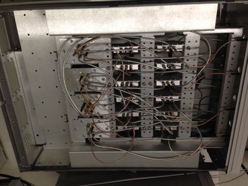
Figure 1: 2x10 full cross bar switch matrix
Insertion loss
Insertion loss plays an important role in many applications. In receiver applications, the effective sensitivity of the system is reduced by the amount of insertion loss. In system applications where the additional power needed to compensate for the loss (e.g. using amplifiers) may not be readily available, possibly due to cost or space constraints, low insertion loss will be the crucial element. Different switch technologies exhibit different insertion loss performance. Electro-mechanical switches which have the lowest loss (up to 26.5 GHz), are suitable for these types of applications.
Isolation
Good isolation prevents stray signals from leaking into the desired signal path. In other words, an unwanted signal needs to be attenuated before it has an opportunity to reach a particular test port. High isolation is especially crucial in measurement systems where signals are consistently being routed to and from a variety of sources and receivers through various switch test ports. If these stray signals are allowed to filter through, measurement integrity is severely compromised. An electro-mechanical switch would provide the best isolation performance (isolation of a switch from a leading vendor would typically be greater than 120 dB from DC to 26.5 GHz) compared to the solid state switches
Switching speed
The measurement of switching speed is based on 10 to 90% RF, using a high-speed generator and an oscilloscope. Switching speed has been and will continue to be one of the main strengths of GaAs FET switches. With ideal driver circuits, GaAs FET IC switches have been shown to switch within < 1 ns (die level). Looking into the future, the emergence of InGaAs material is expected to push the switching speed well into the sub-nanosecond region. Fast switching speed is important in ATE industries where product (testing) through-put is of paramount importance. It is especially important in applications that require the stacking of multiple switches in series. Another new technology usage is in the automotive industry, namely for Adaptive Cruise Control (ACC) and Collision Avoidance Systems (CAS), where high-frequency transmitting and receiving switching rates need to be thoroughly analyzed. As shown in Table 1, the switching time for a solid state (hybrid) switch is the fastest, followed by the solid state (PIN) switch and electro-mechanical switch.
Operating life
The operating life of a switch is specified as the minimum number of cycles (the number of times it switches from one position to another and back) before the switch starts to fail (i.e. where it no longer performs up to the minimum specifications). Switch operating life is crucial when the switch is being integrated into test and measurement instruments or systems which require thousands of switching cycles for a single round of measurements. In this context, solid state switches would be the preferred choice.
Mean time between failure (MTBF)
Mean time between failure (MTBF) is a reliability statistic used as a general indicator of product reliability. It is the arithmetic mean (average) time between failures of a repairable product or system expected over the life of the product. Caution: MTBF is not the expected time to first failure. Typically a RF switch vendor will provide an MTBF figure for your reference. Generally, you can obtain the point estimate in usage hours of the MTBF, and assumed number of hours/year of operation used in the calculation from a switch vendor.
It’s important to be aware that MTBF does not equate to the expected trouble?free period of operation and it is not the “useful life” of the equipment.
MTBF is a statistical calculation and is probabilistic in nature, i.e. it applies to the expected averages across a larger population of equipment, not individual instances.
MTBF is sometimes used in the calculation of spare capacity and spare part requirements. For the reasons noted above, the use of MTBF to accomplish such calculations is not recommended. A more effective plan is to calculate system uptime using reliability modeling tools such as parametric or nonparametric statistical methods.
Operating life and Reliability
The reliability of a switch or switch matrix depends on the operating life of each of its switches and on the total number of switches used. It’s always advisable to use high reliability EM switches to ensure seamless operation. The following is a comparison of replacement frequencies for long operating life switches and switches with a lower specified lifetime in an example application.
Switch operating life/ reliability comparison
This example is a high-volume component or module test application in which switches experience 5,000 closures per 8-hour day (10 closures/min.).
Using high reliable switches:
Replacement frequency = 5 million / 5,000 = 1,000 days = ~2.7 years
Using switches with a lifetime of 1 million cycles:
Replacement frequency = 1,000,000 / 5,000 = 200 days = 6 months
Note that many switch manufacturers do not specify the number of cycles over which the switch is guaranteed to meet specifications, but the number of cycles to destruction. Reliable switch vendor guarantees that its switches will meet all specifications for a minimum of x million cycles.
Repeatability
Repeatability is a measure of the changes in insertion loss or phase for a switch matrix path from cycle to cycle over time. Repeatability ensures accurate test results. S-parameter repeatability is critical because it cannot be calibrated out with test software. Low insertion loss repeatability reduces sources of random errors in the measurement path, which improves measurement accuracy. The repeatability and reliability of a switch guarantees measurement accuracy and can cut the cost of ownership by reducing calibration cycles and increasing test system up time.
CONCLUSION
Selecting the right switch is extremely important for your RF and microwave measurement applications. We have discussed key considerations to help you select and build your own switch matrix based on your application needs. When equipped with the knowledge of available RF switch solutions, application requirements, and performance tradeoffs, engineers can effectively choose between life expectancy and cost without sacrificing the test system performance.
Related Resources:
Keysight Technologies
Switching Solutions for research and development, design validation, manufacturing
Application Note
http://literature.cdn.keysight.com/litweb/pdf/5990-6169EN.pdf
www.keysight.com/find/switches