
In the past few years, the development of In-based devices has enabled receiver systems with record noise temperatures and low power consumption. Incoming Sb-based devices promise to achieve their lowest noise at even lower power consumption. Both technologies, although not yet mature, are usually adequate for designers working with very low noise requirements and very low power consumption. Nevertheless, for some applications, these requirements are critical and a specific technology has to be applied to fulfill such conditions.
In radioastronomy, the lowest noise of the receiver system is always the cornerstone around which that system is designed, since the required integration time to reach a certain signal-to-noise ratio is proportional to the square of the receiver noise. Usually, the system noise requirements are below 20 K of equivalent noise temperature, Te, which can only be achieved if the receiver is cooled down to cryogenic temperatures.1,2
In order to design and test the different systems, the microwave engineers working in radioastronomy applications have to design and set-up a cryogenic facility in which to carry out reliable measurements. Therefore, these engineers have to gain knowledge in cryogenic related issues, which are far out of their professional training.
This article deals with practical issues related to designing and setting-up a small cryogenic facility that enables the ability to take reliable measurements. Calculations of the thermal load for designing the cryostat are presented, together with some advice regarding materials, cables and sensors. Finally, the cold-attenuator technique for measuring Te of available low noise amplifiers (LNA), cooled down to cryogenic temperatures in the designed facility, is described.

Figure 1 One stage closed-cycle refrigerator scheme.
Closed-cycle Helium Refrigerator
Achieving such low temperatures is accomplished using commercially available closed-cycle helium refrigerators. These refrigerators are based in the Gifford-McMahon cooling cycle.3,4 A source of compressed gas is connected to the cylinder through a regenerator and inlet valve (see Figure 1). The regenerator extracts heat from the incoming gas, stores it, and then releases it to the exhaust gas. Another valve is in the exhaust way to the compressor. When the inlet valve is open and the exhaust valve closed, the high-pressure gas goes through the regenerator, where it is cooled, then reaches the cylinder, where the displacer inside the cylinder moves to one end of the cylinder. When the inlet valve is closed and the exhaust valve is open, the gas expands and cools the load. The remaining low-pressure gas is pushed to the exhaust way by the displacer, going through the regenerator, from where the gas receives heat. The gas finally reaches the compressor where it is compressed to start the cycle again.
The first problem for the engineer arises when the refrigerator needs to be selected. There are many cryostats available, but all of them are characterized with the thermal load they can cool at the different stages and temperatures. These kinds of refrigerators have two stages. The first stage is usually cooled down to temperatures of approximately 77 K and the second stage, where the circuits are anchored for testing, reaches temperatures down to 10 K. The purpose of the first stage is to isolate the second stage from the hot refrigerator outer walls, which are at room temperature, approximately 296 K.

The selection of the cryostat is based on the cooling power needed by the user; therefore, the total thermal load has to be calculated prior to purchasing the refrigerator. On the other hand, the cryostat has to be known before designing the box (Dewar) where the measurements are going to be carried out. Table 1 shows the main characteristics of two cryogenic systems from Advanced Research Systems (ARS) working at 60 Hz. The model DE-210AE has recently been purchased to overcome the cooling limitations of the former model DE-202AF in the laboratory.

Figure 2 Exploded view of the cryogenic system.
Thermal Load Calculation
The following calculations are based on the system shown in Figure 2. This figure shows the refrigerator cold-head for the model DE-210AE together with the designed elements that complete the system: elements 6, 8, 17 and 18 make the Dewar; elements 3, 9, 13 and 14 form the radiation shield in the first stage; and element 11 is the second stage base where the circuits are attached.
To obtain the total thermal load in the system four different mechanisms have to be considered: heat conduction through the coaxial and DC-bias cables; heat radiation between surfaces at different temperatures; heat conduction by the residual gas inside the Dewar; and dissipation due to circuit power consumption.
Conduction Thermal Load Calculation
Cryogenic systems involve great temperature gradients. Since the thermal conductivity of materials is variable with temperature, the integral of the thermal conductivity over the temperature range has to be calculated. Equation 1 gives the thermal load due to conduction.4,5 This equation has to be applied in each element going into the Dewar, generally coaxial and DC-bias cables

where A is the conductor cross-section, L is the conductor length, K(T) is the temperature-dependent thermal conductivity of the material, and T1 and T2 are the temperatures at both ends. Plots of the thermal conductivity integrals for common materials are published in the literature.4,6,7 Moreover, the National Institute of Standards and Technology (NIST) provides equations for the thermal conductivity of common materials.8 According to Equation 1, small-section and long cables made with low thermal conductivity materials are preferable. For coaxial cables, stainless-steel outer and inner conductors are the best option. If losses are a concern, a BeCu inner conductor may be selected.
Radiation Thermal Load Calculation
Radiation is produced between two bodies within visual range of each other, separated by a medium that does not absorb this energy. The net rate of heat transfer from one surface at T1 to another surface at T2 can be calculated from Equation 26
where σ is the Stefan-Boltzmann constant, 5.6710-8 Wm-2K-4, A1 is the surface area of one of the bodies, FA is a shape and orientation factor for the two bodies relative to area A1, and FE is the emission and absorption factor for the two bodies. If the surface of one body is small or enclosed by the surface of the other body, then FA = 1. The parameter FE is given by Equation 3

where ε1 and ε2 are the emissivities of the inner and outer surfaces, respectively. These emissivities depend on the temperature and surface finish. Table 2 gives some average values at room temperature for common materials. In general, aluminum and stainless-steel are chosen for Dewar manufacturing. Polished surfaces are preferable since the thermal load reduction, which has to be calculated both at the first and second stage, is noticeable.

Conduction by Residual Gas Thermal Load Calculation
Once the temperature inside the cryostat is low enough to produce the condensation of the remaining gas, the cryogenic vacuum is reached. In such a situation, the heat exchanged by this kind of conduction is negligible. Therefore, in a well-designed system there is no need to calculate the thermal load due to conduction by residual gas.
On the other hand, if leaks are present in the system, the thermal load due to this process may be dominant over the other loads, making it impossible to reach the desired low temperature. Equation 49 gives a simplified way to calculate the heat exchanged between two parallel surfaces of area A at temperatures T1 and T2

where P is the pressure of the remaining gas (in Pascal), a0 is a non-dimensional coefficient and K1 is a gas dependent constant. For air, K1 can be set to 1.2. The coefficient a0 is always less than 1, so it can be set to 1 to consider a worst case scenario. Playing around with numbers, it can be seen that for pressures below 10-4 mbar the thermal load in this case is negligible in both stages. Therefore, when selecting the vacuum pump for the cryostat, a system that reaches pressures well below 10-4 mbar is advisable.
Dissipation Thermal Load Calculation
Devices or circuits cooled in the cryostat are a source of heat since part of the energy they receive from bias lines is dissipated in the second stage, where the device under test is anchored. To obtain the thermal load in this case, the DC power dissipated by the circuit must be calculated.

Summary of Thermal Load Calculations
Table 3 shows the calculated thermal loads at both stages for the designed cryogenic system, considering a remaining gas pressure of 10-5 mbar. According to the calculations in the table, it is clear that only the system DE-210AE considered previously fulfills the power requirements to achieve the desired temperatures. The thermal load in the first stage of model DE-202AF would be so high that this stage could not reach the temperature of 77 K, which would produce an increase in thermal load over the second stage, preventing this stage to be cooled below 20 K.
Other Issues for Designing Cryogenic Systems for MW Applications
In previous calculations, some characteristics of materials such as thermal conductivity or emissivity have been taken into consideration, so the selection of materials is a concern when designing the system. For the Dewar, stainless-steel is commonly used since it shows some advantages over other materials. It does not suffer from oxidation and is easily electro-polished, which reduces the effective surface and therefore the gas absorbed by the surface is also reduced. Another advantage is that it can be easily soldered to obtain reliable high vacuum joints, which facilitates the fabrication of home-made designs. The main drawback of stainless-steel is its weight. When weight may be a problem, aluminum is the best alternative. Aluminum is more fragile, so it needs more thickness to get the same rigidity as stainless-steel; even so the weight reduction is noticeable. The drawback of aluminum is that it is more prone to leaks in the joints; that is the reason why polishing and gold-plating are advisable.
For the radiation shield attached to the first stage, materials with high thermal conductivity and low emissivity are needed, since they need to reduce the radiation absorbed and reemitted to the second stage. Aluminum and copper are usually used in this thermal shield. Once again, polishing and gold-plating is advisable in both materials.5
Cables, sensors and circuits need to be attached to the different stages to be cooled down. When attached, a thermal resistance appears in the joints, which can produce a high temperature gradient between parts. This effect is because the contact is made only in some discrete points instead of the whole surface, even on the smoothest surfaces. One way to improve the thermal conductivity is to increase the applied force on the joint, but there are other options that give better results. The best way to improve thermal conductivity is to increase the total effective contact area by introducing or applying a soft material in the joint. Gold-plating the parts increases this effective area, but better results are found if an Indium foil is introduced in the joint. Nevertheless, the best results are obtained applying Apiezon® N10 vacuum grease between parts.4
Temperature sensors are needed to characterize the experiment and to control the temperature inside the cryostat. There are many types of sensors that are suitable for these purposes, but Si-based diode sensors are commonly used since they offer some advantages: they cover the whole temperature range of interest; they follow a standard curve so they are easily interchangeable; they offer good accuracy without calibration; and they are not very expensive. Model DT-670 from LakeShore11 is used in the designed system.
Finally, RF feedthroughs are an important issue, since they limit the bandwidth of measurements in the system. Feedthroughs installed in the Dewar window covers allow coaxial cables to connect to the circuit. Hermetic bulkhead adapters are preferable for these feedthroughs since they have to keep high vacuum in the chamber. The designed system is mounted with model 34_SMA-50-0-3/111_NE from Huber+Suhner,12 which limit the bandwidth up to 18 GHz. There are some other options for measurements up to 40 GHz like model 25-925-2040-90 from SRI,13 model 34_SK-50-0-54/199_NE from Huber+Suhner and model R127.753.000 from Radiall. These last two options are not available from their webpages, but they have been reported to show good performance in cryogenic Dewars.14
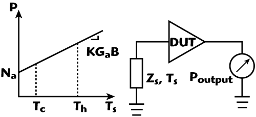
Figure 3 Noise power at the linear system output Na is the noise generated by the DUT.
Cold-Attenuator Technique
Most of the noise measurement techniques, both at room and cryogenic temperatures, are based on the noise linearity of two-port linear circuits.
If a noise source capable of generating two different noise powers is available, then it is easy to calculate the noise generated by the device under test (DUT), when there is not a noise source connected to it, Na. This technique is known as Y-Factor (see Figure 3).15 In cryogenics the problem arises because the two noise powers generated by the source, Tcold and Thot, are far from the DUT noise temperature and measurement error may be quite large. In the cold-attenuator technique, an attenuator is placed in front of the DUT and cooled inside the Dewar, which reduces the noise powers presented at the DUT input. The main advantages of this technique are the following:16
- There are no mechanical switches and neither noise source exchange: therefore, fast and broadband measurements are facilitated.
- The change of noise source output impedance from one state to another is minimized due to the cryogenic path to the DUT. With a 20 dB attenuator, the effect of impedance change is negligible.
- The insertion loss of the input coaxial line to the attenuator has negligible effect over the noise measurement error.

Figure 4 Cold-attenuator technique set-up.
The cold-attenuator technique set-up is shown in Figure 4. A noise source with high excess noise ratio (ENR), from Agilent Technologies, provides the noise power to the system. The parameters Ti mean physical temperatures, while Tei mean equivalent noise temperatures and Li are the insertion losses of the different elements. The purpose of the isolator is to match impedances, avoiding reflected waves that ruin the measurement; the LNA is for minimizing the influence of the noise figure meter, which usually has a big noise figure.
After calibrating at the calibration plane and if all the Tei and Li have been previously calculated, then the equivalent noise temperature of the DUT can be obtained through Equation 5.17

LNA Noise Measurement
Six units of LNA model CRYO10-4292-014 from Caltech (Pasadena, CA, USA) have been measured. One is shown in the photograph of Figure 5. These LNAs have a 6 to 18 GHz bandwidth with over 30 dB gain and approximately 8 K equivalent noise temperature over the whole band, when cooled down to 18 K, according to the data provided by the manufacturer.

Figure 5 Measured Caltech LNA.
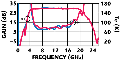
Figure 6 Gain and noise results at 296 K from Caltech (blue) and the present system (red).
Figure 6 shows the gain and noise measured at room temperature, compared to the results from Caltech. For clarity, only the mean value of the six units is plotted. At cryogenics, the amplifiers have been measured in the Dewar presented in this article, together with the refrigerator model DE-202AF. That is the reason why the measured ambient temperature was only 24 K. The mean values obtained applying the cold-attenuator technique in all the units are plotted in Figure 7, together with results from Caltech at 18 K. A photograph of the measurement set-up is shown in Figure 8, with a detailed view of the cold-attenuator elements in Figure 9. The cryogenic results are within 2 K of the data provided by the manufacturer; the difference may be produced by different ambient temperatures as well as measurement uncertainty.
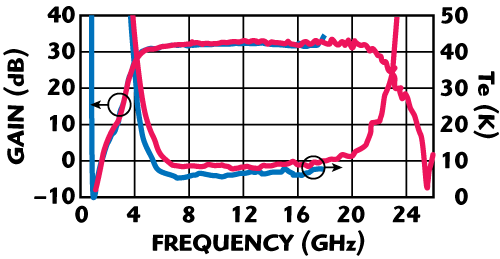
Figure 7 Gain and noise results at cryogenic temperatures for Caltech (blue) and the present system (red).

Figure 8 Measurement set-up in the designed system.

Figure 9 Close view of the attenuator and LNA assembled in the Dewar.
Taking into account all the error sources during the measurements and assuming that these errors are uncorrelated, then the resultant uncertainty can be calculated as the square root of all the uncertainties squared and summed. Typically, this gives a total uncertainty less than ±2 K.17 If needed, an extensive approach to uncertainty calculation can be made using a Monte Carlo analysis.18
Conclusion
The main points to be considered when designing a cryogenic facility, from the microwave engineering point of view, have been presented in this article. The thermal load calculation process is showed in detail as well as some valuable advice regarding materials, cables, sensors and adapters. All this knowledge has been applied to the design of a small system that permits reliable measurements. The performance of the designed facility has been tested with six LNAs manufactured by Caltech. The results show less than 2 K difference with the noise data provided by the manufacturer, which is within the measurement uncertainty.
Acknowledgments
This work has been supported by the Ministerio de Educación y Ciencia (Spain) under Space National program ESP2004-07067-C03-02, Astronomy and Astrophysics program AYA2007-68058-C03-03 and FPI grant BES-2005-6730. The authors would like to thank Centro Astronomico de Yebes (CAY, Guadalajara, Spain) for invaluable technical support and Dewar guidelines, and also the Instituto Astrofisico de Canarias (IAC, Canary Islands, Spain) for providing the LNA for the measurements campaign and Sander Weinreb for sharing Caltech results.
References
1. J.D. Pandian, L. Baker, G. Cortes, P.F. Goldsmith, A.A. Deshpande, R. Ganesan, J. Hagen, L. Locke, N. Wadefalk and S. Weinreb, "Low-noise 6 to 8 GHz Receiver," IEEE Microwave Magazine, December 2006, pp. 74-84.
2. W.A. Imbriale, S. Weinreb and H. Mani, "Design of a Wideband Radio Telescope," IEEE 2007 Aerospace Conference, Big Sky, MT.
3. "CTI Cryostat Technical Manual," CTI-Cryogenics, Helix Technology Corp.
4. J.G. Weisend II, Handbook of Cryogenic Engineering, Taylor & Francis, Eds., 1998.
5. G. Behrens, W. Campbell, D. Williams and S. White, "Guidelines for the Design of Cryogenic Systems," Electronic Division Internal Report, No. 306, NRAO, Charlottesville, VA, March 1997.
6. T.M. Flynn, Cryogenic Engineering, Marcel Dekker, 2005.
7. Lakeshore Temperature Measurements and Control Catalog, 2004.
8. E.D. Marquardt, J.P. Le and R. Radebaugh, "Cryogenic Material Properties Database," 11th International Cryocooler Conference, June 2000.
9. J.D. Gallego, "Amplificadores Refrigerados de Muy Bajo con Transistores GaAs FET para la Frequencia Intermedia de Receptores de Radioastronomica," PhD Thesis, Universidad Complutense de Madrid, 1992.
10. www.apiezon.com.
11. www.lakeshore.com.
12. www.hubersuhner.com.
13. www.sriconnectorage.com.
14. www.microwave101.com/cgi-bin/messageboard/YaBB.pl?num=1158567881.
15. Fundamental of RF and Microwave Noise Figure Measurements, Agilent AN 57-1, Agilent Technologies, 2004.
16. J.E. Fernandez, "A Noise-temperature Measurement System Using a Cryogenic Attenuator," TMO Progress Report 42-135, November 1998.
17. N. Wadefalk, A. Mellberg, I. Angelov, M.E. Barsky, S. Bui, E. Choumas, R.W. Grundbacher, E.L. Kollberg, R. Lai, N. Rorsman, P. Starski, J. Stenarson, D.C. Streit and H. Zirath, "Cryogenic Wide-band Ultra-low-noise IF Amplifiers Operating at Ultra-low DC Power," IEEE Transactions on Microwave Theory and Techniques, Vol. 51, No. 6, June 2003, pp. 1705-1711.
18. J.D. Gallego and M.W. Pospieszalsky, "Accuracy of Noise Temperature Measurements of Cryogenic Amplifiers," Electronics Division Internal Report No. 285, NRAO, Charlottesville, VA, 1990.
Juan L. Cano received his telecommunications engineering degree from the University of Cantabria, Spain, in 2004. He is currently working towards his PhD degree at the same university, designing MIC and MMIC LNAs at microwave and millimeter-wave frequencies and other hardware for radioastronomy receivers. His areas of interest include very low noise amplifiers and systems working at room and cryogenic temperatures.
Eduardo Artal received his engineer and Dr. engineer in telecommunication degrees from the Technical University of Catalonia, Barcelona, Spain, in 1976 and 1982, respectively. Since 1990, he has been a Professor at the University of Cantabria, Santander, Spain, where he was manager of the telecommunication engineering course from 1990 to 1994. His areas of interest include microwave circuits and systems, including MMICs up to 50 GHz. His current research interests include low noise millimeter-wave amplifiers and receivers.