
An ultra high resolution radar is one of many promising areas of UWB applications because of its inherent nature of ultra wide bandwidth.1 In theory, UWB radar could achieve the ultra high range resolution of up to 2 cm if a single antenna could cover the whole UWB frequency bandwidth of 7.5 GHz from 3.1 to 10.6 GHz. Thus, a compact UWB antenna design with an ultra wide bandwidth and high-directive radiation has been a challenging problem in radar applications. The bowtie antenna is known to be one of the most common UWB antennas since it has many advantages in its small size, light weight, wide bandwidth and omni-directional radiation pattern.1-6
To achieve the ultra wide bandwidth performance, several types of bowtie antennas have been reported for UWB communications and radar applications such as patch-type,2 slot-type,3-4 coplanar waveguide (CPW) and coplanar stripline types.3-6 However, the bandwidth of a typical bowtie antenna with a compact size is still not sufficient to cover the whole UWB frequency band within an acceptable level of return loss.
More importantly for high resolution radar applications, an omni-directional antenna’s performance can be degraded by multi-target, multi-path reflections from the unwanted objects in or around the radiation direction. However, most existing UWB bowtie antennas still exhibit a bi-directional or omni-directional radiation pattern.2-6 Recently, the patch-type bowtie antenna has been reported for unidirectional radiation,7 but the antenna size is large and its bandwidth is still narrow in covering the whole ultra-wideband frequency. Thus, the design of a new unidirectional UWB bowtie antenna is highly desirable for ultra high resolution radar and communication applications.
A novel bowtie antenna with and without a pyramidal corner reflector is proposed and the performances are compared for UWB radar applications by satisfying two critical requirements: much lower return loss less than -10 dB over the 100 percent UWB frequency band and unidirectional radiation pattern with a high front-to-back ratio.
Shaped Bowtie Radar Antenna Design

Figure 1 Base model structure of the proposed UWB bowtie antenna.

Figure 2 Pyramidal reflector of the proposed bowtie antenna.
A high-performance bowtie radar antenna with unidirectional radiation has been designed for covering the whole UWB frequency band using a new method of a shaped tapered antenna design approach. The geometry of the base model of the proposed horn-shaped bowtie antenna is shown in Figure 1. From the wave dispersion characteristic point of view, the shaped bowtie radiating element can give wider gain bandwidth than ridged square and triangular-shaped conventional types of bowtie elements.6 A pair of horn-shaped bowtie radiating elements on a dielectric substrate is symmetrically arranged on a single-sided copper clad laminate. A CPS is then placed with a tapered strip width and narrow gap between shaped bowtie radiating elements, since this structure is less dependent of the characteristic impedance matching.5 For the unidirectional design requirement, a horn-shaped pyramidal reflector (see Figure 2) is separately designed and compactly attached to the back of the bowtie plate for reducing the back radiation and giving more unidirectional gain to the target direction. To implement the shaped tapered bowtie antenna design approach, most of the step discontinuities from the conventional type of triangular bowtie radiating element were removed, and the discrete shape of the stripline feed was smoothly tapered in order to enhance the impedance-bandwidth of the antenna. Through a parametric simulation and search (using MicroStripes by Flomerics Ltd., UK), it was found that the bandwidth increases with the increase of L1, L2 and W1, W2 within a certain limited compact size. It was also observed that the impedance bandwidth is changing depending on the width and gap of the tapered stripline with the different lengths of L4 and L5. The overall dimensions of the horn-shaped bowtie element were obtained as follows: L1=15.8 mm, L2=11.8 mm, L3=1.0 mm, W1=6.6 mm, and W2=9.6 mm, θ=104 degrees. The dimensions of the stripline extended to the bowtie element are selected as: L4=14.1 mm, L5=3.2 mm, W3=1.4 mm, W4=2.8 mm and W5=2.8 mm, respectively. The stripline gap between a pair of bowtie elements is selected as S1=2 mm. The overall size of the bowtie antenna plate is 48 mm (x direction) × 32 mm (y direction) × 1.6 mm (-z direction), which is very compact.
For the unidirectional radiation requirement, the dimensional depth and stripline distance of the pyramidal corner reflector is found to affect the return loss, bandwidth, resonant frequency and radiation characteristics. The depth of reflector, d, and stripline distance, S2, were finally selected as S2=4 mm and d=20 mm, respectively. The overall size of the antenna with a reflector is 60 mm (x direction) × 44 mm (y direction) × 20 mm (-z direction), which is compact in size, light weight and easy to fabricate for any UWB radar applications; thus, this size can possibly be integrated within the size of the ultra-wideband device.
Fabrication and Experiment

Figure 3Fabricated bowtie antenna without reflector (a) and with reflector (b).
An experimental horn-shaped bowtie antenna with and without the pyramidal reflector was fabricated, as shown in Figure 3. To implement the bowtie radiating element, the single-sided 35 micron copper-clad substrate (FR4 board) was chosen with a thickness of 1.6 mm and dielectric constant of 4.55. For achieving unidirectional radiation with a high front-back ratio, a horn-shaped pyramidal corner reflector element was made of thin copper sheet with the thickness of 0.1 mm, and a 4 mm-slot was spaced between the bowtie plate and a pyramidal corner reflector. The return loss, S11, of the antenna was measured using a vector network analyzer (HP 8722ES). The radiation pattern and gain-transfer function, S21, were measured in an anechoic chamber using two identical bowtie antennas separated by a distance well into the far-field range for all frequencies under consideration. For the radiation measurement, the transmitting bowtie antenna was situated on a turn table and rotated 360 degrees in steps of 1 degree while simultaneously sweeping the whole UWB frequency bands of 2 to 12 GHz, recording 1601 frequency points. A set of measured S21 data for each frequency was then selected in order to produce the full radiation pattern at selected frequencies in the UWB band.
Result and Discussion

Figure 4 Return loss comparison with and without reflector.
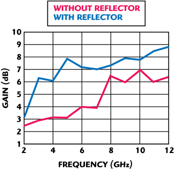
Figure 5 Antenna gain comparison with and without reflector.
The return loss of the fabricated bowtie antenna with and without a reflector was compared with the predicted and measured results, as shown in Figure 4. As can be seen, the simulated return loss of the antenna without a reflector shows less than -10 dB over the very wide frequency range of 2 to 11.3 GHz, except for the frequency band of 8.2 to 9.4 GHz, which allows a bit higher than -10 dB. However, the measured return loss for the tapered bowtie antenna is less than -10 dB over the complete UWB frequency band of 3 to 10.8 GHz, and even less than -12 dB over 3.2 to 10.5 GHz, showing a better gain-bandwidth performance. There is a slight difference between the simulated and the measured return loss, but the degree of the return loss is still within the requirements in both cases and their trends are similar to each other. For unidirectional radiation performance, the same optimized design of the antenna with the reflector shows a much wider bandwidth from 3.06 to 11.7 GHz at the same threshold level of return loss of -10 dB. It is observed that a smoothly tapered bowtie antenna without a discrete step in the stripline can give more wide gain bandwidth and lower return loss, compared to the simply ridged shape of bowtie antennas with a discrete step as in the case of conventional triangular or rectangular-type antennas. The overall performance of the predicted return loss with and without a reflector shows a good agreement with the measured results that satisfies the critical design requirements for covering the whole UWB frequency bandwidth from 3.1 to 10.6 GHz defined by the FCC. The antenna gain was obtained by the simulation in both cases, as shown in Figure 5. The gain of the bowtie antenna without a reflector ranges from 2.5 dBi at 3 GHz to 6.9 dBi at 10 GHz, which consistently increases with the increase in frequency over the whole UWB frequency band. The gain of the antenna with a reflector, however, increases from 6.5 to 8.5 dBi, almost double the case without a reflector, which gives more highly directional gain to the target direction.
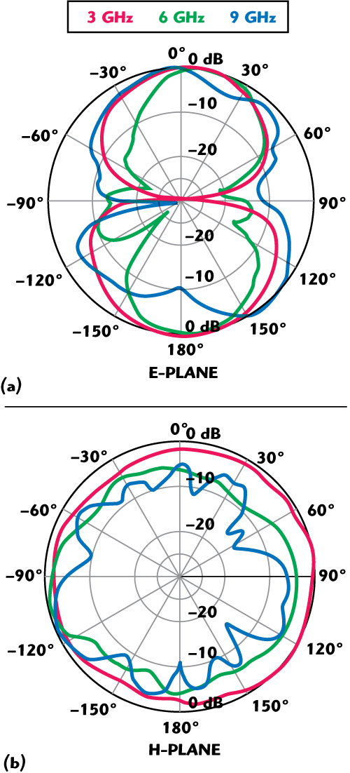
Figure 6 Radiation pattern of the antenna without reflector.

Figure 7 Radiation pattern of the antenna with reflector.
The radiation pattern for a bowtie antenna with and without a pyramidal reflector was measured in the E-plane and H-plane at the selected frequencies of 3, 6 and 9 GHz from the whole UWB frequency ranges, as shown in Figures 6 and 7, respectively. The trend of the broadband radiation of the antenna without a reflector is changing from bi-directional (forward and backward lobes) to quasi omni-directional as the frequency, while the bowtie antenna with a reflector shows a good unidirectional radiation performance compared to the case without a reflector. The measured radiation pattern of the reflector backed antenna shows a high front-to-back radiation ratio of 30 dB at the lower frequency band. However, as the operating frequency increases, the main beam tends to squint slightly in the off-broadside direction. This is an inherent limitation of the UWB antenna due to the finite physical size of the bowtie element in accommodating the whole ultra-wideband frequency. The overall antenna pattern shows the unidirectional radiation to the desired target direction, which is useful for high-directive radar imaging applications.
Conclusion
A new horn-shaped bowtie antenna with a corner reflector that is fed by a tapered planar stripline is designed and fabricated with a compact size for lower return loss, wider gain bandwidth, and unidirectional radiation for UWB radar and medical imaging applications. The measured bandwidth covers over 100 percent of the whole UWB frequency band over 3 to 11.7 GHz at a return loss of less than -10 dB, and the radiation pattern is unidirectional with stable high front-to-back ratio over the frequency band. These high performance and compact geometry features can be attractive for UWB radar imaging and directional communication systems applications.
Acknowledgement
This paper was supported in part by a “Korea Aerospace University Faculty Research Grant” during visiting research at University of Oxford, UK, in 2008. The author would like to thank D. Edwards for his advice and A. Hassanein for his experimental assistance.
References
1. B. Allen, M. Dohler, E. Okon, W. Malik, A. Brown and D. Edwards, Ultra-wideband Antennas and Propagation for Communications, Radar and Imaging, John Wiley & Sons Ltd., UK, 2007.
2. K. Kiminami, A. Hirata and T. Shiozawa, “Double-sided Printed Bowtie Antenna for UWB Communication,” IEEE Antenna and Wireless Propagation Letters, Vol. 3, 2004, pp. 152-153.
3. M. Miao. B. Ooi and P. Kooi, “Broadband CPW-fed Wide Slot Antenna,” Microwave Optical Technology Letters, Vol. 25, No. 3, 2000, pp. 206-211.
4. C. Huang and D. Lin, “CPW-Fed Bowtie Slot Antenna for Ultra-wideband Communications,” IET Electronics Letters, Vol. 42, September 2006, pp. 1073-1074.
5. G. Bindu, V. Hamsakkutty, A. Lonappan, J. Jacob, V. Thomas, C. Anadan and K. Mathew, “Wideband Bowtie Antenna with Coplanar Strip Line Feed,” Microwave and Optical Technology Letters, Vol. 42, June 2004, pp. 222-224.
6. A. Mehdipour, K. Mohammadpour and R. Sebak, “Modified Slot Bowtie Antenna for UWB Applications,” Microwave and Optical Technology Letters, 50, 2008, pp. 429-432.
7. M. Ameya, M. Yamamoto, T. Nojima and K. Itoh, “Leaf-shaped Element Bowtie Antenna with Flat Reflector for UWB Applications,” IEICE Trans. Comm., Vol. E 90-B, No. 9, September 2007, pp. 2230-2238.
Young K. Kwag is currently a professor at the School of Electronics and Telecommunications Engineering, Korea Aerospace University. He has been with the Agency for Defense Development (ADD) as a Division Head and Principal Researcher for over 25 years in the R&D projects of radar systems, SAR and radar signal processing. He was a visiting research professor in the Department of Engineering Science, University of Oxford, UK, from 2007-2008. He has been a chairman of the Radar Society of KEES and session chair and reviewer of the IEEE/IET international radar conference. His areas of interest include radar signal processing, synthetic aperture radar imaging and ultra-wideband radar antenna.