
Monopole antennas are used in mobile communications. A monopole antenna is a very simple and efficient radiating element.1 It is well known that the smaller the size of the antenna, the lower its efficiency and narrower its bandwidth (a few percent).2 A 36 percent bandwidth enhancement of a monopole antenna using a parasitic normal-mode helix3 and a planar monopole antenna with a bandwidth of 44 percent4 have been reported. A small size, top-loaded monopole antenna was described in the literature,5 but its operational frequency bandwidth is very narrow (a few percent).
In this article, a wide and multi-band top- and center-loaded monopole antenna with a ring-shaped plate is proposed. The ring-shaped plate is used to enhance the impedance matching and to increase the antenna gain by causing a low radiation resistance in the usable band. Moreover, a dual-top loading, consisting of a center-loading (a ring-plate) and a top loading (an umbrella-type), acts to reduce the antenna size and enhance the bandwidth, respectively. This antenna also offers wideband and multi-band characteristics.
Antenna Structure and Experimental Results

Figure 1 Antenna structure.
The structure of the proposed wide and multi-band dual-top loading monopole antenna with a ring-shaped plate is shown in Figure 1. It consists of a post-type monopole, a dual dielectric post (dielectric posts 1 and 2), a dual-top load (a ring-plate and an umbrella-type element), a ring-shaped plate on the ground plane, a circular ground plane and a 50 Ω N-type connector. The lower dielectric post (post 1) is placed between the ground plane and the aluminum post, improving the coupling. The aluminum monopole consists of a ring-shaped loading plate and a post-type element inserted between the dielectric posts 1 and 2. The two dielectric posts, made of polyacetal with a dielectric constant εr= 3.7, also improve the coupling between the lower aluminum post and the umbrella-type top element. As a result, a much wider bandwidth is obtained than without the dielectric posts. The 50 Ω N-type connector is attached to the dielectric post 1, through a large hole in the ground plane. The umbrella-type element is composed of four Al rods, which are oriented 90° from each other and attached to the upper dielectric post with a polycarbonate screw (εr= 3.0).
Lul and hul are the lengths of the horizontal and vertical sections of the umbrella element, respectively. Dul is the diameter of the aluminum rod. Rd1, Rd2 and hd1, hd2 are the radii and the heights of the first and the second dielectric posts, respectively. Hm is the height of the aluminum post. Htl is the height of the center-loading ring-plate and hrp is the height of the ground ring-plate. Rtl and Rrp are the radii of the center-loading ring-plate and the ground plane ring-plate, respectively. Rg is the radius of the circular ground plane. The top loading is used to reduce the height of the antenna. The additional ring-shaped plate also leads to obtain a wider bandwidth and a higher gain than the conventional top loading monopole structures. The top loading reduces the high-angle radiation, which leads to a decrease of the multi-path fading, and to increase the service area.6 Figure 2 shows a photograph of the fabricated antenna.
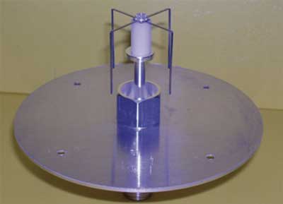
Figure 2 Photograph of the antenna.
The fabricated antenna dimensions are as follows: Lul= 18 mm, hul= 28 mm, Dul= 2.5 mm, htl= 2.8 mm, Rtl= 6 mm, hd1= 3 mm, Rd1= 3.5 mm, hm= 35 mm, hd2= 15 mm, Rd2= 4 mm, hrp= 14 mm Rrp=10 mm, Rg= 55 mm. The 50 Ω N-type connector is located on the z-axis to feed the proposed antenna. The post-type element is used to enhance the impedance matching. The circular ground plane is made of aluminum, 1.0 mm thick.
Figure 3 Measured VSWR.
The measured VSWR as a function of frequency is shown in Figure 3. The measured impedance bandwidth shows a lower band of 1.62 to 3.05 GHz (61.2 percent) with a center frequency of 2.335 GHz and a higher band of 3.78 to 5.96 GHz (44.8 percent) with a center frequency of 4.87 GHz for a VSWR of less than 2.0. This antenna offers wideband and multi-band characteristics. The proposed antenna can be applied to PCS, DCS, IMT-2000, WLL, DMB and home-network operations.
Figure 4 Measured radiation pattern in the y-z plane.
After calibration using a horn antenna, the radiation pattern in the far field was measured. An investigation of the radiation pattern characteristics of this antenna shows them to be similar to a conventional monopole. In Figure 4, the measured y-z plane radiation pattern of the proposed antenna is a bi-conical radiation pattern. The x-z plane radiation pattern is omni-directional without distortions, as illustrated in Figure 5.
Figure 5 Measured radiation pattern in the x-z plane.
The measured gain versus frequency for the monopole antenna is given in Figure 6. The measured maximum gain of the proposed antenna is approximately 3.2 dBi.
Figure 6 Measured antenna gain.
Conclusion
In this article, a low profile wideband dual-loading monopole antenna with a ring-shaped plate is presented. The ring-shaped plate on the ground plane is used to enhance the impedance matching and to increase the antenna gain. Two dielectric posts are used to improve the coupling between the lower aluminum post and the umbrella type element, leading to an enhanced bandwidth. The dual-loading consists of the ring-plate and the umbrella top, which acts to reduce the antenna height and enhance the bandwidth, respectively. A lower band of 1.62 to 3.05 GHz (61.2 percent) and a higher band of 3.78 to 5.96 GHz (44.8 percent) have been measured for a VSWR less than 2.0. This antenna offers wideband and multi-band characteristics. The proposed antenna can be applied PCS, DCS, IMT-2000, WLL, DMB, home- and hospital-network operations, and medical instrument applications.
References
1. M.W. Melvin, P.C. Ctephen, C.L. Cho and J.W. Warren, Monopole Elements on Circular Ground Plane, Artech House Inc., Norwood, MA, 1987.
2. K. Fujimoto and J.R. James, Mobile Antenna Systems Handbook, Artech House Inc., Norwood, MA, 1994, pp. 65-70.
3. J.I. Moon, S.O. Park and K.Y. Park, “Broadband Sleeve Monopole Antenna for Dual-band PCS/IMT-2000,” Electronics Letters, Vol. 36, 2000, pp. 1829-1830.
4. Y.W. Chow, E.K.N. Yung and H.T. Hui, “Bandwidth Enhancement of Monopole Antenna by Using a Parasitic Normal-mode Helix,” International Journal of Electronics, Vol. 88, 2001, pp. 557-593.
5. H. Jiang and H. Arai, “FDTD Analysis of Low Profile Top Loaded Monopole Antenna,” IEICE Transactions on Communications, Vol. 85-B, No. 11, November 2002, pp. 2468-2475.
6. C.A. Balanis, Antenna Theory, John Wiley & Sons Inc., Hoboken, NJ, 1997.