
The wireless and satellite communications communities have always been looking for power efficient radios. However, the power efficiency is greatly dominated by the efficiency of the RF power amplifier (PA) in the transmitting path. Recently, most of the communication systems being deployed or to be deployed in the near future use time-varying envelope signals. With such signals, PAs are required to operate in their back-off region to meet the required linearity. This linearity is defined either by the adjacent channel power ratio (ACPR) or the error vector magnitude (EVM) in the context of wireless applications or noise power ratio (NPR) in satellite communications. The setting of the back-off level is generally a function of the input signal’s peak-to-average power ratio (PAPR). Unfortunately, the power efficiency of the amplifier decreases when the back-off level increases. In most cases, this leads to the design of very low-efficiency amplifiers that require large DC power modules, with bulky thermal dissipators for fixed terminals or have short battery life in mobile terminals.
From the base station prospective, these linear and low-efficiency amplifiers turn out to be very costly to manufacture and very expensive for the telecommunication operators who run the infrastructure. Linearization techniques are being used to improve the achievable power efficiency. However, the resulting power efficiency is still in the range of 15 to 30 percent.1-3 Recent advances in semiconductor process technologies such as GaN- and SiC-based devices4 are making the design of highly efficient switching mode RF power amplifiers a feasible solution for such applications. To be able to use such power amplifiers, their design has to be considered closely together with the system architecture in order to ensure optimal system-level performance. This implies that conventional transmitters’ architectures have to be adapted or modified to be able to integrate this new type of amplifier.
Several attempts have been made to adjust standard architectures or even to propose alternative architectures that are based on switching mode amplifiers. Among these, one can distinguish sigma-delta modulator-based transmitters,5,6 digital power amplifier concept-based architecture7 and linear amplification using nonlinear component (LINC) transmitter architecture.8-11 Indeed, the use of class D, class E and class F switching mode RF power amplifiers as well as their derivative classes in such architectures are considered as enabling technologies for the realization of highly efficient transmitters for satellite communications, and 3G and beyond applications.
In this article, an overview of the actual state-of-the-art in power amplification and software-based transmitters is presented, along with emerging trends. First, the state of power amplifier technology and the performance of the different architectures are discussed. Second, advanced SDR-based transmitter architectures are introduced. Conclusions are then drawn and prospects for futures radio systems are discussed.
State-of-the-Art Amplifier Technology
Continuously Driven Amplifiers
Several solutions have been proposed and are used to partially circumvent the power efficiency limitations in continuously driven amplifiers such as class A, class AB and balanced or push-pull amplifiers. The most commonly adopted solutions consist of using continuous mode power amplifiers, mainly class AB power amplifiers, combined with one of the well established linearization techniques such as feedback, feed forward, RF predistortion and baseband digital predistortion.12 The selection of the adequate technique in most cases is dependant on the application/standard, which dictates the targeted level of linearity to be reached.

Despite the fact that most of these technologies can lead to an acceptable level of nonlinearity correction for power amplifiers, the only compatible solution with SDR-based transmitters is the baseband digital predistortion, considered as an enabling technology for 3G and beyond radio systems. This technology, in most cases, allows the radio designer to meet the linearity requirements, but the power efficiency of these systems is currently limited to approximately 25 percent.2
Linearization Techniques
A memory polynomial predistorter, shown in Figure 1, is utilized to pre-compensate the static nonlinearity as well as the electrical memory effects of the RF transmitter.13 The predistortion function of each branch of the multi-branch polynomial predistorter is defined by

f(u(t–i)) = u(t–i) (ai0+ai1|u(t–I)|
+… + ai,p–1|u(t–i)|p–1
As a demonstration of the capability of the digital predistortion technique, a three-carrier WCDMA signal is synthesized and applied to the transmitter to assess the performance of the described memory predistorter. The comparison results of the output spectra shown in Figure 2 demonstrate that the memory polynomial predistorter can effectively suppress the out-of-band emission as well as the in-band distortion caused by the electrical memory effects.
Load Modulated/Doherty Amplifiers
In load-modulated PAs, the load impedance seen by the transistor varies depending on the input power level. The load modulation mechanism is designed and controlled in such a way that the overall performance of the amplifiers is improved in comparison with the case of a PA having a constant load. A generic block diagram of load-modulated amplifiers is presented in Figure 3.
The Doherty power amplifier is among the architectures that beneficially use the load modulation mechanism. Doherty amplifiers that are capable of handling envelope-varying signals are perceived as a dazzling way of improving the efficiency of the power amplification stage. This is accomplished through an active load-pulling effect seen by the carrier amplifier as an extension of its saturation point. Therefore, the efficiency of the Doherty amplifier is effectively increased in the back-off zone, without compromising its maximum output power.3,14–16
Figures 4 and 5 show a photograph of a 16 W Doherty amplifier for 3G applications and its performance, respectively. As shown, Doherty amplifiers have a mild nonlinearity that can be improved using DPD, but improved power efficiency.
Switching Mode Amplifiers

Several attempts have recently been made to build switching mode RF power amplifiers (class D, class E and class F) that greatly boost the power efficiency. Such amplifiers can theoretically permit close to 100 percent power efficiency. However, this power efficiency degrades as the operating frequency increases, due to the parasitic reactances, the nonzero switching resistance and the switching time.
Traditionally, class D amplifiers, which consist of two active devices that are alternately switched on and off, are very popular at audio frequencies. At RF frequencies, however, the output shunt capacitance of the transistor causes significant losses. Newly proposed current-mode class D (CMCD) amplifiers adapt the class D concept to RF applications by partially eliminating these losses.17
Alternatively, in class E amplifiers, the zero voltage switching operation mode is advantageous since it eliminates the shunt capacitance losses of class D amplifiers. Furthermore, optimal harmonic loading used in class F amplifiers leads in general to 10 to 20 percent enhancement in the power efficiency of continuously driven class AB and class B power amplifiers.18,19 Recent realizations of switching mode amplifiers have reported power efficiencies ranging from 40 to 80 percent for frequencies from 1 to 2 GHz.17,20
These amplifiers have been constructed primarily in LDMOS18 and HBT17,19 technologies. However, HBT technology has been used more widely, due to its high reliability and monolithic integration that make it suitable for satellite communication as well as wireless communication systems. Switching mode amplifiers are thus considered potential candidates to replace continuously driven amplifiers in advanced transmitter architectures, such as those based on the LINC concept, the envelope elimination and restoration (EE&R) technique, the delta-sigma modulator and the Doherty amplifier.
Advanced SDR-based Transmitter Architectures
LINC Transmitters
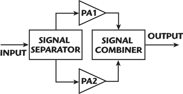
The LINC concept uses two nonlinear RF PAs to form a linear amplification system. This is achieved by driving the two RF PAs with signals having constant envelope and time-varying phases. The phases are controlled in such a manner that the combination of the outputs of both PAs produces a system output with the desired amplitude and phase modulation.8,9
This architecture is very sensitive to gain and phase imbalance between the two signal paths. In addition, it has limited dynamic range and the overall power efficiency is greatly affected by the type of RF combiner used and the statistics of the signal.10 Indeed, the average efficiency enhancement of a LINC-based amplifier decreases as much as the signal’s PAPR increases.11 Figure 6 is a block diagram of LINC-based transmitters. The two constant-envelope signals generated to drive the nonlinear power amplifiers are given by

In such a case, and when the two paths are perfectly balanced, the output signal is a linear amplified replica of the input signal, and is given by


where
G = gain of the power amplifier
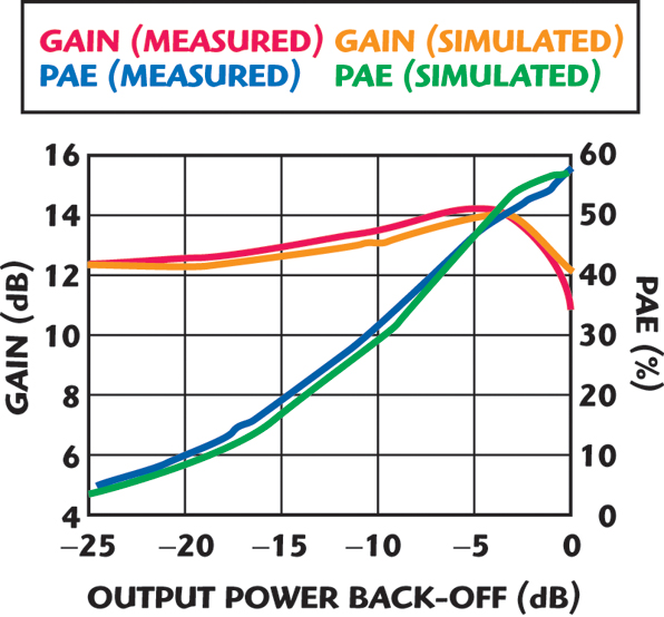
Recent development and implementations of LINC-based architectures demonstrated the ability of this technique to provide very good linearity as well as significantly improved power efficiency for WiMAX applications, as shown in Figures 7 and 8.21
EE&R Transmitter
The EE&R technique uses a limiter to transform the original input signal into a constant envelope signal. The amplitude information is then recovered by varying the bias of the power amplifier.22,23 This technique has a limited dynamic range, is sensitive to delay mismatch and is also limited by the DC/DC converter speed and power handling requirements.23

However, polar modulation technology using the EE&R technique has been implemented commercially for handheld low power terminals, creating a single, universal, multimode handset radio transmitter, which can support GSM/GPRS and EDGE signals, as well as the WCDMA signal. Polar modulation is well poised to enable development of multimode handsets for these multiple air interface standards.
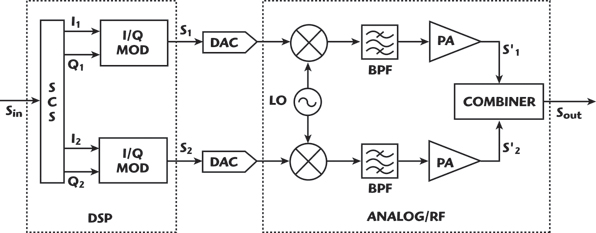
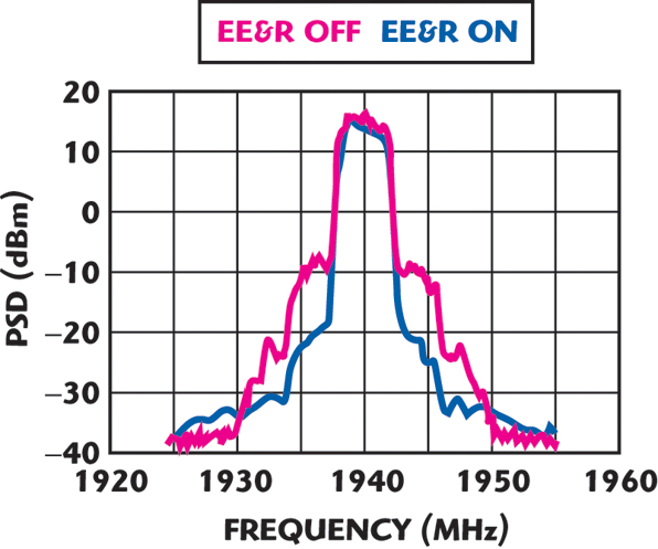
A generic block diagram of a polar modulation transmitter is shown in Figure 9. Figure 10 shows the output spectrum of EE&R handheld-based transmitters driven with 3G signals.24
Delta-sigma Modulator-based Transmitter
The delta-sigma modulator also offers a valuable potential solution to convert analog complex modulation information of envelope varying signals into digitally coded pulses to drive the switching mode amplifiers.5,6 However, the conventional architecture requires tremendous sampling rate, which exceeds the capability of current technology for 3G and beyond applications.
A block diagram of a typical bandpass ΔΣ transmitter is shown in Figure 11 along side with the signal waveforms at the different points in the system. It consists of a ΔΣ analog-to-digital converter (ADC), a switching-mode power amplifier and a bandpass filter. The filter is required to restore the analog signal before transmitting the information to the antenna.
The RF input signal is digitized by the ΔΣ-ADC to a two-level signal. The bandpass ΔΣ modulator maps the baseband signal to a range around an intermediate frequency that is equal to a quarter of the sampling frequency. The quantization noise is spectrally shaped and normally falls outside of the bandpass.5,6 However, practical implementation generally results in a relatively high noise floor that affects the quality of the signal and its linearity.
Figure 12 shows the output spectrum of a ΔΣ transmitter that uses a second-order ΔΣ modulator designed for 800 MHz applications, when driven with a two-tone signal. Since the output of the ΔΣ modulator has fixed amplitudes, a highly efficient switching-mode power amplifier, typically an RF class S power amplifier, can be used for amplification without introducing harmonic distortions.
Prior to transmission toward the antenna, the original signal is restored by filtering the amplified RF digital signal with a high quality factor bandpass filter. The bandpass filter is required to attenuate the out-of-band quantization noise and to suppress all higher harmonics. Hence, this transmitter topology has the potential to amplify digitally modulated signals with large peak-to-average-power ratios (PAPR) while maintaining high power efficiency and high linearity.
Conclusion
Emerging technologies and planned applications worldwide are increasingly using bandwidth-efficient, non-constant envelope modulation schemes such as MC-CDMA and OFDM. These modulation schemes call for the development of spectrum and power efficient SRD transmitters that can support multiple air-interface standards. In this article, advanced power amplification architectures that have the potential to meet both the linearity and power efficiency requirements for emergent broadband wireless and satellite communications were presented.

Typical performance of digitally predistorted continuously driven power amplifiers and Doherty amplifiers have been discussed and their performance assessed. The state-of-the-art in switching mode amplifier design was briefly presented. Finally, the principle and limitations of power amplification stages and transmitter architectures appropriate for use in switching mode power amplifiers were discussed. This included LINC and EE&R transmitters, and delta-sigma modulator-based transmitters.
Acknowledgment
This work was supported by the Natural Sciences and Engineering Research Council of Canada (NSERC), Canada Research Chairs (CRC) and the Informatics Circle of Research Excellence (iCORE).
References
1. C.C. Jeonghyeon, Y. Jaehyok, J. Kim and K. Bumman, “Optimum Design of a Predistortion RF Power Amplifier for Multicarrier WCDMA Applications,” IEEE Transactions on Microwave Theory and Techniques, Vol. 52, No. 2, February 2004, pp. 655–663.
2. W. Wangmyong, M.D. Miller and J.S. Kenney, “A Hybrid Digital/RF Envelope Predistortion Linearization System for Power Amplifiers,” IEEE Transactions on Microwave Theory and Techniques, Vol. 53, No. 1, January 2005, pp. 229–237.
3. J. Sirois, S. Boumaiza, M. Helaoui, G. Brassard and F.M. Ghannouchi, “A Robust Modeling and Design Approach for Dynamically Loaded and Digitally Linearized Doherty Amplifiers,” IEEE Transactions on Microwave Theory and Techniques, Vol. 53, No. 9, September 2005, pp. 2875–2883.
4. L. Larson, P. Asbeck and D. Kimball, “Challenges and Opportunities for Compound Semiconductor Devices in Next Generation Wireless Base Station Power Amplifiers,” IEEE Compound Semiconductor Integrated Circuit Symposium Digest, Palm Springs, CA, October 2005.
5. I. Galton and H.T. Jensen, “Oversampling Parallel Delta-sigma Modulator A/D Conversion,” IEEE Transactions on Circuits and Systems II: Analog and Digital Signal Processing, Vol. 43, No. 12, December 1996, pp. 801–810.
6. G.I. Bourdopoulos and T.L. Deliyannis, “High-order Vector Sigma-delta Modulators,” IEEE Transactions on Circuits and Systems II: Analog and Digital Signal Processing, Vol. 47, No. 6, June 2000, pp. 493–503.
7. P. Nagle, R.M. Husseini, A. Grebennikov, W.K.M. Ahmed and F. McGrath, “A Novel Wideband Digital Power Amplifier and Transmitter Architecture for Multimode Handsets,” 2004 IEEE Radio and Wireless Conference Proceedings, Atlanta, GA, September 2004, pp. 171–174.
8. H. Chireix, “High Power Outphasing Modulation,” Proceedings of the IRE, Vol. 23, November 1935, pp. 1370–1392.
9. D.C. Cox, “Linear Amplification with Nonlinear Components,” IEEE Transactions on Communications, Vol. 23, No. 12, December 1974, pp. 1942–1945.
10. C.P. Conradi and J.G. McRory, “Predistorted LINC Transmitter,” IEEE Electronics Letters, Vol. 38, No. 7, March 2002, pp. 301–302.
11. F. Raab, “Efficiency of Outphasing RF Power Amplifier Systems,” IEEE Transactions on Communications, Vol. 33, No. 10, October 1985, pp. 1094–1099.
12. F.H. Raab, P. Asbeck, S. Cripps, P.B. Kenington, Z.B. Popovic, N. Pothecary, J.F. Sevic and N.O. Sokal, “Power Amplifiers and Transmitters for RF and Microwave,” IEEE Transactions on Microwave Theory and Techniques, Vol. 50, No. 3, March 2002, pp. 814–826.
13. J. Kim and K. Konstantinou, “Digital Predistortion of Wideband Signals Based on Power Amplifier Model with Memory,” IEEE Electronics Letters, Vol. 37, No. 23, November 2001, pp. 1417–1418.
14. W.H. Doherty, “A New High Efficiency Power Amplifier for Modulated Waves,” Proceeding of the IRE, Vol. 24, September 1936, pp. 1163–1182.
15. M. Iwamoto, A. Williams, P.F. Chen, A.G. Metzger, L.E. Larson and P.M. Asbeck, “An Extended Doherty Amplifier with High Efficiency Over a Wide Power Range,” IEEE Transactions on Microwave Theory and Techniques, Vol. 49, No. 12, December 2001, pp. 2472–2479.
16. S. Bumjae, C. Jeonghyeon, K. Jangheon, Y.Y. Woo and B. Kim, “Linear Power Amplifier Based on 3-way Doherty Amplifier with Predistorter,” 2004 IEEE MTT-S International Microwave Symposium Digest, Vol. 3, pp. 2027–2030.
17. H. Tsai-Pi, A.G. Metzger, P.J. Zampardi, M. Iwamoto and P.M. Asbeck, “Design of High Efficiency Current-mode Class D Amplifiers for Wireless Handsets,” IEEE Transactions on Microwave Theory and Techniques, Vol. 53, No. 1, January 2005, pp. 144–151.
18. F. Lepine, A. Adahl and H. Zirath, “A High Efficient LDMOS Power Amplifier Based on Inverse Class F Architecture,” 34th European Microwave Conference Proceedings, Amsterdam, The Netherlands, October 2004, pp. 1181–1184.
19. N. Le Gallou, J.Y. Touchais, J.F. Villemazet, A. Darbandi, J.L. Cazaux, A. Mallet and L. Lapierre, “High Efficiency 45 W HPA for Space Application,” 34th European Microwave Conference Proceedings, Amsterdam, The Netherlands, October 2004, pp. 181–184.
20. S. Zhang, J. Cao and R. Mcmorrow, “E-PHEMT, Single Supply, High Efficient Power Amplifiers for GSM and DCS Applications,” 2001 IEEE MTT-S International Microwave Symposium Digest, Vol. 2, pp. 927–930.
21. M. Helaoui, S. Boumaiza, F.M. Ghannouchi, A.B. Kouki and A. Ghazel, “A New Mode-multiplexing LINC Architecture to Boost the Efficiency of WiMAX Up-link Transmitters,” IEEE Transactions on Microwave Theory and Techniques (to be published in February 2007).
22. F.H. Raab, B.E. Sigmon, R.G. Myers and R.M. Jackson, “L-band Transmitter Using Kahn EER Technique,” IEEE Transactions on Microwave Theory and Techniques, Vol. 46, No. 12, December 1998, pp. 2220–2225.
23. F. Wang, D.F. Kimball, J.D. Popp, A.H. Yang, D.Y. Lie, P.M. Asbeck and L.E. Larson, “An Improved Power-added Efficiency 19 dBm Hybrid Envelope Elimination and Restoration Power Amplifier for 802.11g WLAN Applications,” IEEE Transactions on Microwave Theory and Techniques, Vol. 54, No. 12, December 2006, pp. 4086–4099.
24. S. Reed, Y. Wang, S. Toutain, H. Cam, F. Huin and F.M. Ghannouchi, “Performance Optimization of DSP Driven and Dynamically Biased Power Amplifiers for 3G Handset Applications,” 2003 European Conference on Wireless Technology (ECWT’2003) Proceedings, Munich, Germany, pp. 41–44.

Fadhel Ghannouchi is currently a professor in the electrical and computer engineering department of the Schulich School of Engineering at the University of Calgary and director of the Intelligent RF Radio Laboratory. He presently holds an iCORE /Tier 1 Canada Research Chair in RF Radio Technology. He has held invited positions at several academic and research institutions in Europe, North America and Japan. He has provided consulting services to a number of microwave and wireless communications companies. His research interests include microwave instrumentation and measurements, nonlinear modeling of microwave devices and communications systems, design of power and spectrum efficient microwave amplification systems, and design of intelligent RF transceivers for wireless and satellite communications.