
Early flexible coaxial cables, circa World War II, typically consisted of a bare copper round wire inner conductor, solid or stranded, and a full density extruded polyethylene insulating dielectric making up the core. A copper round wire braid formed the outer conductor. The braid wires could be bare copper or tinned. Silver-plated copper was used for “higher” frequencies. The braiding process consisted of a group of round wires, usually five or six, laid side by side to create a ribbon-like conductor, which in turn was formed into a basket weave to surround the core. This process resulted in an approximately 90 percent coverage of the surface, which was, for the most part, adequate to serve as an outer conductor from an attenuation perspective. Sometimes a second braid was applied over the first braid to obtain better shielding. An extruded polyvinyl chloride jacket completed the cable, providing mechanical protection for the braided outer conductor.
RF transmission lines for government (military) use had achieved a degree of standardization, including a numbering system. RG-/U was the designator, with RG referring to “radio guide.”1 It should be noted here that flexible cables were used then only when necessary and then generally at lower frequencies. Rigid coaxial lines consisting of silver-plated brass or copper tubing and rods were the preferred construction used to carry microwave power, especially at higher frequencies.
In the November 1961 Microwave Journal article "RF Leakage Characteristics of Popular Coaxial Cables and Connectors, 500 MC to 7.5 GC" by John Zorzy and R.F. Muehlberger,
The triaxial cavity, which by the authors’ admission did not capture all the modes of leakage present, certainly advanced the technology. They argue most of the energy will probably end up flowing axially along the cable (as in the case of a long wire antenna, ed.) At this point in time, RF leakage was just becoming an issue, as systems were slowly growing in complexity and becoming more sensitive to unwanted RF energy. Interestingly, RG-8 and RG-58 are still available today for low frequency applications such as CATV and communications.
In the early ’70s, W.L. Gore & Associates (Gore) was producing a product called Multi-Tet, which began as a ribbonized arrangement of parallel conductors. These conductors, which were individually insulated by wrapping them with full density polytetrafluoroethylene (PTFE) tape, were sandwiched accurately between two layers of PTFE strips. This provided controlled registration of the conductors, allowing the automated connectorization at the terminating ends. As time went on, customers wanted coaxial cables included in these arrangements. These coaxes were made reminiscent of the early cables, although extruded PTFE was becoming more popular because of its higher temperature rating. Gore, on the other hand, was using a PTFE tape wrapping process, as opposed to extrusion, which permitted better impedance control and uniformity. These products were used for low frequency applications—less than 100 MHz.
Gore began experimenting with a “foil” layer as the first shield layer, instead of the traditional braid. The foil was a metallized (aluminum) layer on a polyester tape, which was helically wrapped on the core. It was necessary to run a “drain” wire under the foil to maintain a continuous ground from turn-to-turn, and to allow for termination in the connector. An outer round wire braid held everything together and enhanced the shielding effectiveness. This was a good low frequency solution and was used popularly for intermediate frequency (IF) and digital applications. From a microwave perspective, however, it failed to provide good shielding, lacking the full surround of metal, and also gave rise to poor attenuation and impedance performance.
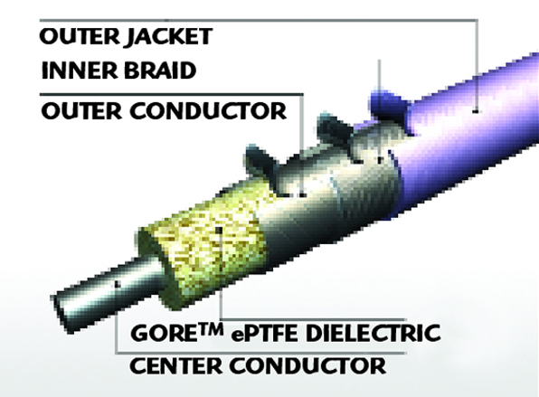
Fast forward to 1975. The state-of-the-art flexible microwave coaxial cables now consist of a center conductor wrapped with layers of PTFE tape and an outer shield where the individual braid wires have been replaced with ribbons of silver plated-copper foil. Sometimes the PTFE tape was perforated to lower the εr, which in turn reduced the attenuation due to a larger inner conductor for a given impedance.
The following equations explain how this comes about.
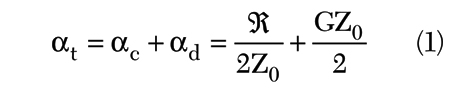
where
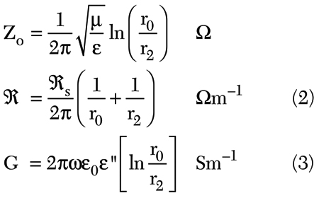
where
r0 = radius of the outer conductor, meters
rj = radius of the inner conductor, meters
μ = μrμ0, permeability, Henrys/meter
ε = εrε0, dielectric constant, Farads/meter
ε" = loss factor of the dielectric
Rs = skin effect surface resistivity of the conductors, Ω
ω = frequency, radians/second
αt = total attenuation of a TEM transmission line, Nepers/meter
αc = attenuation due to conductor loss, Nepers/meter
αd = attenuation due to dielectric loss, Nepers/meter
= 8.686 (αc+αd), dB/meter
Equation 1 shows the attenuation of a coaxial cable consisting of loss due to the finite conductivity of the metallic surfaces and the loss due to energy dissipated in the dielectric materials. It is assumed no significant RF leakage is present. For a given conductivity, from Equation 3 it is seen that RF resistance is inversely proportional to the radii of the conducting surfaces, so bigger is better. Equation 2 shows that for a given impedance, the ratio of these radii is inversely proportional to the square root of the dielectric constant. A lower dielectric constant produces a smaller ratio. For a given outer conductor radius, a larger inner radius will result and attenuation is reduced. A further reduction takes place as the dielectric material is replaced by air. A benefit of the reduced attenuation is that as more signal gets through the cable, less is converted to heat. This allows for higher power handling for a given size of cable.
RF leakage performance with this construction was still hampered by the inability to obtain 100 percent coverage, but the RF performance of the cable had improved such that it is acceptable to at least 12.4 GHz. Hence, a true flexible microwave cable now existed. Stability with flexure was greatly improved and the PTFE provided lower loss and better power handling characteristics. The flat wire “braid” was often wrapped with a metallized plastic tape to reduce RF leakage, but somewhat at the expense of flexibility
At Gore, engineers Roger Kauffman, who had been working with the Multi-Tet cable, and Don Slothour, who had been responsible for the coax cable, began exchanging ideas about ways to improve their products. Semi-rigid cable, with its solid copper tube outer conductor, was clearly the benchmark for shielding but was not very flexible. Hence, the name semi-rigid.
Their exchanges led to the idea of trying to wrap a true foil (silver-plated copper with no plastic tape) over the core. This would emulate the high shielding effectiveness of the semi-rigid cable, but retain the flexibility of the metallized tapes and braid combinations. Another engineer, Howard Arnold, had already developed specialized tape wrappers for placing layers of PTFE tapes on various wire and cable products. These machines gave good control over the on wire properties of the wrapped layers, at the same time offering a lot of flexibility over standard purchased machines. It was thus a relatively easy task to modify the machines to apply the solid foil over the core. This made the process of determining the geometry and tension of the foil considerably easier. A solution was found to satisfy both the “feel” of the cable and its electrical properties. As before, the use of a round wire braid over the foil layer insured the mechanical integrity of the foil layer and later proved to be the key for good connector attachment. But this was just the beginning.
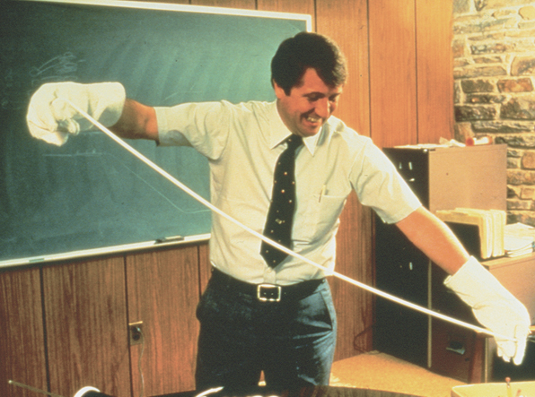
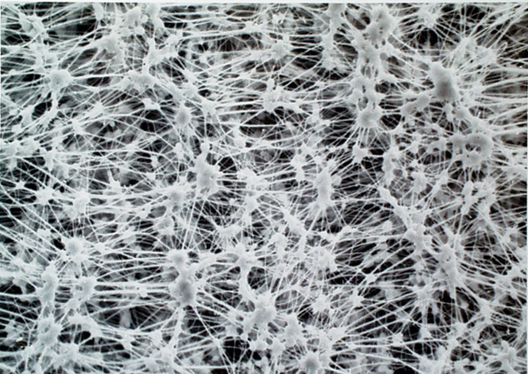
Bob Gore, the son of the company’s founders, had found a way to stretch PTFE in a controlled fashion (see Figure 1) such that a uniform structure of “nodes and fibrils” was produced (shown in Figure 2), giving rise to a new and exciting material—expanded PTFE or ePTFE. ePTFE was eventually used to make one of Gore’s most popular consumer products: GORE-TEX® Fabric. The microporosity of the ePTFE dramatically altered many of the electrical and mechanical properties of its parent. Notably, for the microwave world, the dielectric constant, εr, went from 2.1 to between 1.7 and 1.3, depending on the processing. Loss tangent, tan Δ, was proportionally reduced, depending on the air/PTFE ratio. Fortunately, the excellent temperature and chemical resistant properties of the base PTFE were not degraded.
With this new invention, Gore Associates were looking for ways to utilize the new wonder material. Due to Bill and Vieve Gore’s style of leading the enterprise, all ideas were fair game. Ideas from tennis racquet strings to bubblers for aquariums were considered. Bill saw to it that ideas were to be explored for their value on the spot, not just put on a list to be voted on sometime by “management.” With this freedom Don and Roger decided to try ePTFE as the core insulator for cable.
Constructing a cable with an ePTFE core and a foil/braid outer conductor was easy; characterizing the resulting product, however, was not. Finding ways to terminate the resulting product with commercially available connectors for actual sale proved even harder. With the dramatic reduction in εr, the ratio of outer/inner diameter (D/d) resulted in problems with respect to connectors. If you chose the inner conductor diameter as a constant, based on standard AWG wire sizes, the outer conductor outgrew everyday connectors. Conversely, holding the outer conductor diameter constant meant the inner conductor became much larger.
The attenuation per unit length of the cable dropped like a rock compared to previous constructions, so it was crucial to make it possible to produce cable assemblies with this product. Don and Roger approached connector manufacturers for help. “When you get to perhaps 100,000 units per year, then we are interested,” was the response. But help did come, as one manufacturer saw the potential of the performance improvement, offering to assist. Electromagnetic simulators had not yet been invented, as the computers to support them were either still a dream or busy doing more important things. So it took a lot of cut and try for the new cable configuration to marry up to standard connector interfaces. Succeed, agonizingly, they did, and the Gore Microwave Cable Assembly was born. All cables needed a jacket, or outer protection layer, to protect against abrasion and whatever. The microporous ePTFE further needed protections against fluids. Jacketing material could assume almost any color with the addition of dye components. Black and brown were industry standard. Many colors were tried, but purple provided the best results. It was different—no one was making purple cables. So in 1976 Gore introduced its first purple microwave assembly to the world.
But this new product still had a long way to go to be accepted: “What programs are you on?” “Have you been qualified?” But there were those who saw the value and bought in to the lower loss. Westinghouse put Gore cables in the ALQ-119 and 131 pods, and NRL installed GORE™ Microwave Assemblies in a research satellite. This established Gore as space qualified. Credibility was beginning to happen.
The US Navy was charged with developing a system that could deal with a wide range of targets, both water- and air-based simultaneously with a high degree of precision and mission success. The key to this system was a computerized, passive, electronically steered phased-array radar, the SPY-1A, as the primary source of situational awareness.
The radar was to provide a 360° horizon coverage, be manufacturable, and have 20 year (minimum) lifetime under maritime conditions. Approximately 10,000 microwave cables were required to outfit each destroyer/cruiser system. It was necessary that the system be able to operate over a wide temperature range as a precaution. The εr and hence the electrical length vs. temperature characteristic of dielectrics can be a killer in phase sensitive situations. The GORE Microwave Assemblies with its ePTFE-based dielectric, and a nominally 70 percent air content, appealed to the engineers at RCA. PTFE, from a microwave perspective, exhibits a large and nonlinear change vs. temperature. Tempering the PTFE with air, as in ePTFE, proportionally reduces this temperature dependency by a factor of 3 or 4 to 1. That is why GORE Microwave Assemblies were chosen for the next generation SPY-1-B upgraded system. Required was that Gore provide a cable assembly with a given electrical length, but that the electrical length (phase vs. temperature) characteristic be reproducible from lot to lot over a long-term production cycle. This was not easy, as product process variability and improvement can be counter-productive. In other words, when you qualify good, bad or indifferent, that is where you are. Gore produces its own ePTFE from resin pellets and has complete control over the entire process. This allows for tailoring the final product based on specific needs. As a result, Gore was able to meet this challenge and provided a significant number of systems before a radical system redesign eliminated the need for flexible cables.
RF leakage, as it was known in 1961, is now characterized as shielding effectiveness (SE). It was not a big issue then. In those early days, systems were generally simple and power levels were low. But that all changed as technology evolved. Satellites grew more complex with dramatic increases in the number of channels and advances in power amplifier technology raised the ambient RF field levels. The triaxial cavity, while able to evaluate short sections of cable or a connector pair, could not predict performance of a full cable assembly, or a cascade of cables and other components. Further, there was a considerable amount of subjectivity, as the cavity had to be manually tuned for each test frequency. Multi-line connectors were also difficult to characterize, as they could not conveniently be included within the cavity. Making a larger cavity reduced the upper frequency limit of the test due to higher order modes.
Crawford, Koepke, Jesch, Staeger and Bolinger at the National Bureau of Standards, now the National Institute of Standards and Technology (NIST), undertook the task of providing a test system to specifically solve these problems. The outcome was a system called the mode stirred chamber, which resembles a giant microwave oven (see Figure 4). The test specimen is placed in the chamber, and a mode stirrer, not unlike a Casablanca fan, stirs the modes to ensure a complete exploration of coupled fields.
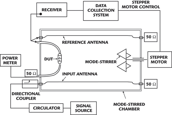
This proved to be a rigorous test, collecting radiation in all directions and configurations. It was now possible to measure the SE of a wide range of specimens from miniature connectors to entire airplanes, over the frequency range of 1 to 18 GHz. Dynamic range of 130 dB or more is possible with this system. With its own mode stirred cavity, Gore was able to characterize cable assemblies to determine how best to achieve a high level of SE. From this knowledge, it was then possible to fine-tune the elements that make up the barrier to leakage of the GORE Microwave Assemblies. This included foil pitch, cross-section size and shape, and the applied tension.
SE of a new cable right out of the box is a good metric. Going a step further, what happens to a cable after it has been installed or heavily flexed? Gore engineers developed a test system that could pinpoint the source of leakage, even in long cables. With this, they are able to analyze “used” or damaged cable assemblies to determine where the barrier had weakened or outright failed. This information is used to further fine-tune the cable to produce acceptable levels of SE.
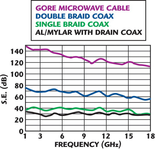
The current accepted industry practice for SE is 90 dBc per foot to 18 GHz. Gore cables routinely exceed 110 dBc regardless of length. Figure 5 shows the typical shielding performance for four different coax cable types. Each type differs only in the construction of the cable’s outer shield. As shown, a Gore microwave cable provides significantly better shielding than braiding or aluminized mylar approaches because of the helically wrapped foil outer shield.
Connectors are sometimes a different issue, as some are better than others. As an indication of how the needs of the microwave community have evolved over time, the 110 dBc is not always sufficient to satisfy some requirements. It is also interesting to note that the 1961 article speaks of 7.5 GHz as if it were some magic number. (The triaxial cavity is capable of 18 GHz and beyond). Today, we work at 110 GHz and find those who would have cables at 160 GHz. It is fortunate that machine shops have kept pace with the microwave industry needs, and are capable of building some of the things we need.
Acknowledgment
The author would like to thank Roger Kauffman for providing information for this article.
Reference
1. G.L. Ragan, Microwave Transmission Circuits, McGraw Hill Book Co. Inc., New York, NY, 1948. 
Harmon Banning, retired Gore Associate, received his BS degree in electrical engineering from the University of Maine in 1961. He had a distinguished career that spanned over 45 years in the RF/microwave industry. He worked for General Electric Co., Andrew Alford Consulting Engineers, Weinschel Engineering Inc. and joined W.L. Gore & Associates in 1987. In November 2007, he was honored with the Automated RF Techniques Group (ARFTG) Career Award.