
Wireless communication systems have been developed to offer higher data transmission, such as the currently popular bands of Wireless Local Area Networks (WLAN), IEEE 802.11b (2.4 to 2.48 GHz) and 802.11a (5.15 to 5.35 and 5.725 to 5.825 GHz). The planar antenna has a simple structure, lower profile and easy manufacture. Therefore, many compact single or dual-band planar antenna designs for the WLAN bands have been proposed.1–4
A compact, CPW feed, monopole antenna using a spiral strip and an inverted L strip, operating at both 2.4 and 5 GHz, has been reported.1 Another compact dual-band antenna, with double L-slits, has also been proposed.2 A CPW-fed circular slot antenna, with a pair of symmetrically positioned T-shaped slits embedded in the back-patch, has been described.3 A 2.4/5 GHz dual-band operation was achieved.
A broadband or a dual-band operation at 2.4/5 GHz was achieved with another compact dual-/multi-band antenna4 by adjusting the location of the microstrip feed and designing a notched shape. However, these designs, with a large overall size, are unsuitable for WLAN bands with USB applications. Recently, a 2.4 GHz meander-line printed antenna5 on a USB WLAN card was presented. But the single band operation is not suitable to WLAN in the 5 GHz band applications.
In this article, a dual-band design of a microstrip-fed monopole antenna is proposed for WLAN USB applications. By properly adjusting the shape of the copper sheet and feed structure, the dual-band design of the proposed antenna, operating at frequencies covering the 2.4/5 GHz WLAN bands, is achieved.
This proposed antenna is suitable for a universal serial bus dongle installation on a laptop. The proximity effect of the metal on the antenna performance is investigated and compared with the printed antenna.
Antenna Design
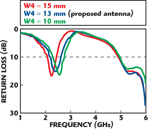
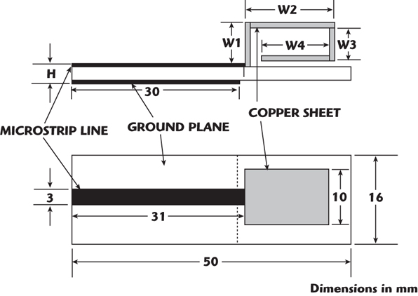
Figure 1 shows the geometry of the dual-band antenna for WLAN USB applications. The proposed antenna is fabricated on an FR4 substrate with a thickness h = 1.6 mm and a relative permittivity ερ = 4.4 with dimensions of 16 x 50 mm. The material of the proposed antenna is a 0.1 mm copper sheet, which is connected to a 50 Ω microstrip line. By using a bent copper sheet, the antenna size can be made compact.
The total height of the proposed antenna is (h + 8 mm) from the ground plane. The dimensions of the proposed antenna are W1 = 8 mm, W2 = 18 mm, W3 = 6 mm and W4 = 13 mm. In addition, four different feed structures on the copper sheet connected to the 50 Ω microsrip line have been investigated, with a 1 mm separation from the ground plane of the FR4 substrate.
The first resonant frequency is determined by the dimensions of the bent copper sheet and the higher resonant mode is excited by varying the feed structure of the copper sheet near the 50 Ω feed line.
Parametric Study and Discussion
Design with Different Shape of the Feeds
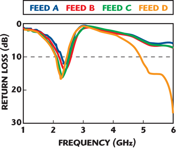
Figure 2 shows the various feed geometries of the proposed antenna. Four feed structures have been tried: rectangular (A), trapezoid (B), two notches (C) and two slits (D). The measured return losses for the different feeds are shown in Figure 3, where W1 = 8 mm, W2 = 18 mm, W3 = 6 mm and W4 = 15 mm.
It can be seen that the higher resonant mode is excited by the feed structure D. The feed structure D was adopted for all the antennas discussed in this article.
Different Values of Copper Sheet Length W4
The measured return losses for different values of length W4 of the copper sheet are shown in Figure 4. It is observed that the length W4 is the important parameter to determine the lower frequency (2.4 GHz band). As W4 decreases, the lower band moves to a higher frequency. On the other hand, the upper frequency (5 GHz band) is insensitive to changes in W4.
Optimized Design
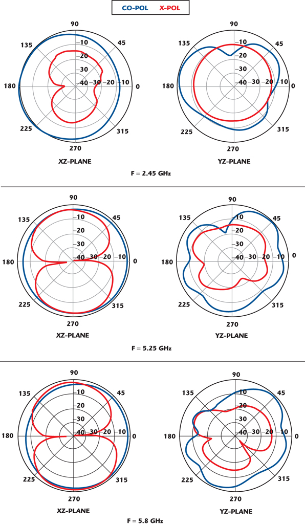
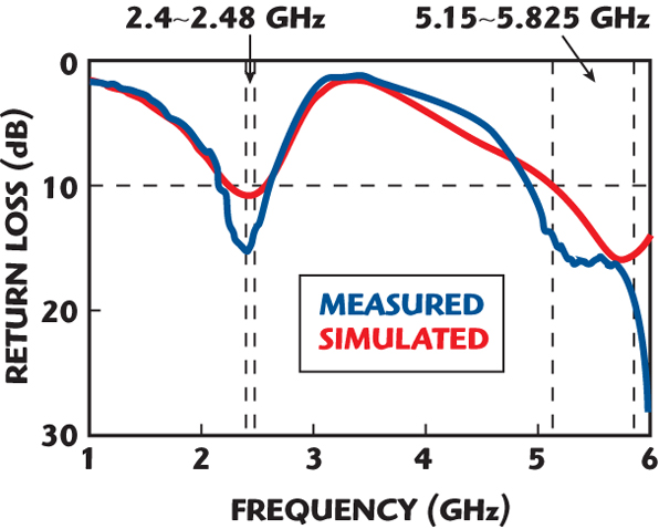
Figure 5 shows the measured and simulated return losses of the proposed dual-band antenna with the following dimensions: W1 = 8 mm, W2 = 18 mm, W3 = 6 mm and W4 = 13 mm. The simulated results were obtained by using the High Frequency Structure Simulator (HFSS). Reasonable agreement between the measured and simulated results is observed.
The obtained impedance bandwidths are 18.9 percent (2.15 to 2.6 GHz) at the lower band and over 19.6 percent (4.93 to 6 GHz) at the upper band, covering WLAN (2.4 to 2.4835 GHz, 5.15 to 5.35 GHz and 5.725 to 5.850 GHz) operating bands. The proposed antenna possesses the advantage of low profile, small size, simple structure and easy manufacture. It is suitable for use in portable devices of wireless applications.
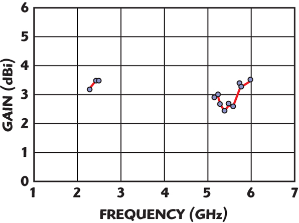
The far field radiation patterns for the proposed antenna were measured in an anechoic chamber. Figure 6 shows the measured peak gain for the dual-band antenna. The 2.4 GHz band (2.3 to 2.5 GHz) has a peak gain of approximately 3.4 dBi; the gain variation is less than 0.3 dBi. For the 5 GHz band (5.15 to 5.8 GHz), the peak antenna gain is approximately 3.3 dBi and the gain variation is less than 0.92 dBi; the gain variation in the proposed antenna is stable.
The measured radiation patterns of the proposed antenna at some typical frequencies are also investigated. Figure 7 plots the measured radiation patterns of the dual-band antenna at 2.45, 5.2 and 5.8 GHz.
The Effect of Metal on the Antenna Performance
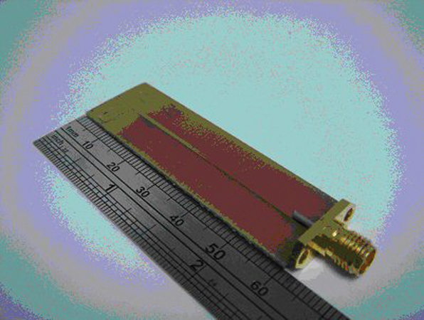
For practical applications, the effects on the impedance bandwidth of adding a copper sheet below the proposed antenna have been investigated. In addition, a printed meander line monopole antenna was fabricated, following the design process described by C.C. Lin, et al.5 A photograph of the printed antenna for WLAN USB is shown in Figure 8.
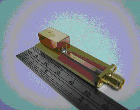
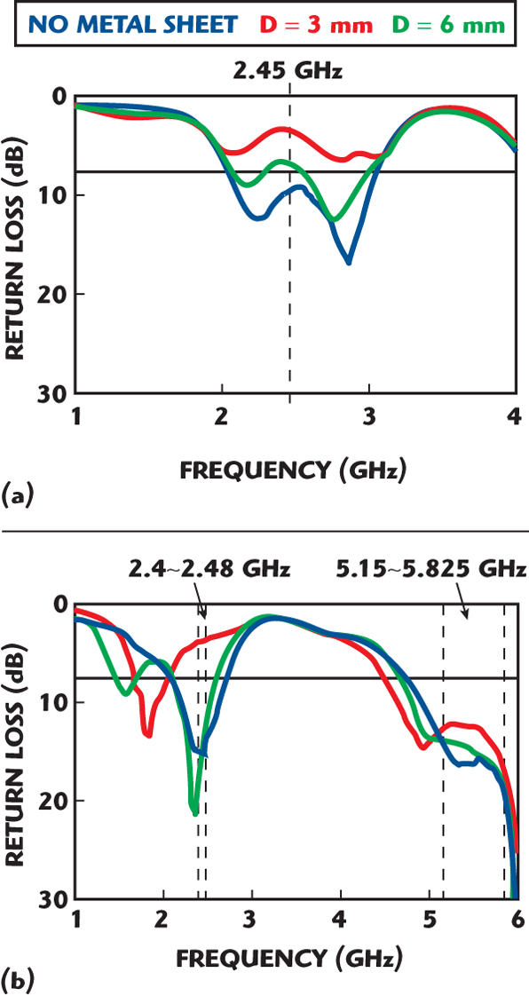
A photograph of the constructed prototype dual-band antenna is shown in Figure 9. Figure 10 shows the measured return loss when adding a metal sheet below the antennas. The parameter d is the distance between the ground of the antennas and a large copper sheet (size 200 x 200 mm). As seen, the printed antenna is significantly affected by adding a copper sheet below the ground plane of the antenna, while for the proposed antenna, adding a copper sheet below the ground plane causes a small frequency shift of the 2.45 GHz band.
The effect of adding a large copper sheet slightly affects the bandwidth performance of the proposed antenna in the 5 GHz band. This is probably because the resonance mode at 5 GHz of the proposed antenna is mainly contributed by the vertical part of the antenna configuration.
Conclusion
In this article, a dual-band, small size and simple configuration USB antenna for WLAN applications was proposed. The dual-band characteristic for the 2.4/5 GHz bands can be achieved by using two slits on the feed structure of the copper sheet. Finally, the proximity effect of a metal on the antenna performance was investigated. The proposed antenna has good radiation characteristics, better than a planar printed antenna, because of its solid radiator.
References
1. T.H. Kim and D.C. Park, “CPW-fed Compact Monopole Antenna for Dual-band WLAN Applications,” Electronic Letters, Vol. 41, 2005, pp. 291–293.
2. T.H. Kim and D.C. Park, “Compact Dual-band Antenna with Double L-slits for WLAN Operations,” IEEE Antennas and Wireless Propagation Letters, Vol. 4, 2005, pp. 249–252.
3. J.Y. Sze, C.I.G. Hsu and J.J. Jiao, “CPW-fed Circular Slot Antenna with Slit Back-patch for 2.4/5 GHz Dual-band Operation,” Electronics Letters, Vol. 42, 2006, pp. 563–564.
4. N. Behdad and K. Sarabandi, “A Compact Dual-/Multi-band Wireless LAN Antenna,” 2005 IEEE Antennas and Propagation Society International Symposium Digest, pp. 527–530.
5. C.C. Lin, S.W. Kuo and H.R. Chuang, “A 2.4 GHz Printed Meander-line Antenna for USB WLAN with Notebook-PC Housing,” IEEE Microwave and Wireless Components Letters, Vol. 15, No. 9, August 2005, pp. 546–548.