

When communication systems are established engineers must account for numerous real world effects and maintain reliable communication systems. Information such as path loss from the transmitter to the receiver, immunity to interference (calculating and testing the effects of non-intended signals on the intended communications signal or effects of a high density of intended signals), multi-path reflections (effects of signals reflected off of buildings/structures/mountains), speed/movement of cars/trains and atmosphere losses.

While real world testing in the exact location of the deployed communication system will yield the best overall information, this is not practical in most cases. Setting up signal conditions in a controlled laboratory environment allows for many different signal situations and repeatable “Communications Interoperability” test results. This also allows the system engineers the ability to adjust hardware performance parameters to yield high reliability communication systems.
Attenuation Matrix units are used as signal simulation tools to simulate interoperability testing. The signal path loss and channel interaction for multiple communication signals are input into the Attenuation Matrix to simulate real world field conditions in a repeatable, controlled laboratory environment.
Aeroflex/Weinschel has designed an Attenuation Matrix configuration to simulate the connectivity between a mobile (train) running along a line of three base stations spaced from 250 to 1000 meters apart (see Figure 1). This test subsystem needed to be able to simulate the variation of the RF signal from the base stations reaching the moving train (as well as the signal from the moving train reaching the base stations) when the train is moving at speeds of up to 250 km/h.

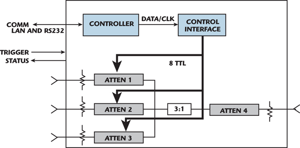
The simulator attenuates the base station signal through three independent attenuators, as shown in Figure 2, then combines the signals. Each attenuator has a dynamic range of 60 dB in 1 dB steps. The operation of the unit is via a RS-232 or LAN interface. ASCII commands are used to input parameters into the controller. Upon receiving a trigger the controller executes the program to simulate the link loss to all three base stations as seen from the train transceiver.
The switching speed of the attenuators limits the resolution of the simulator for extreme situations. The digital attenuators quantize the levels of attenuation in decibels. Figure 3 shows the case of a train, at 250 km/hr, with the base stations 250 meters apart and placed 10 meters from the path. The PIN attenuators step in 1 dB increments and the controller switches the attenuator at a one millisecond rate. The graph shows that for this scenario, the attenuators need to be updated every 28 milliseconds, therefore the time resolution will not be noticeable.

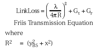
The Roaming System simulator operates by the customer inputting the parameters listed below. These values will generate data to control the attenuators to simulate the signaling link. Each of these parameters is interactive. The parameter ranges listed in Table 1 must be evaluated interactively with all other parameters. The parameters listed use a Friis Equation for calculation of link loss plus the correction factors associated with the antenna. This simulation is for 2D and does not account for multi-bounce or environment. For more advanced link-loss profiles, the user can externally compute the attenuation vs. time profile and directly load this data via RS-232 into the controller data tables for execution, effectively over-riding the built-in function. This allows arbitrary profiles to be generated.

Figure 4 shows the geometry used in the LinkLoss calculation.
For some system simulations the engineering team needs more repeaters to be able to be simulated. Using the configuration shown in Figure 5, six repeaters can be simulated by interconnecting two Roaming Systems.

The Roaming simulator functions as a stand alone simulation system. The LAN or RS-232 control interface is used to load test setup parameters such as mobile position (X or Y position), mobile speed, time, antenna gain and frequency. The system simulates the mobile moving past three repeater sights, thus the three inputs. If the operators would like to simulate more repeater sights multiple roaming simulators can be connected together to perform the test. For up to a six input simulation, the operators must connect the outputs together using a power combiner.
Next the digital status line (indicating the start and stop of a mobile test) is connected from one system to the second system trigger input. This allows both units to start at the same time. The system can then be triggered (or started) either using the hardware trigger input (on the first system) or via a software command.
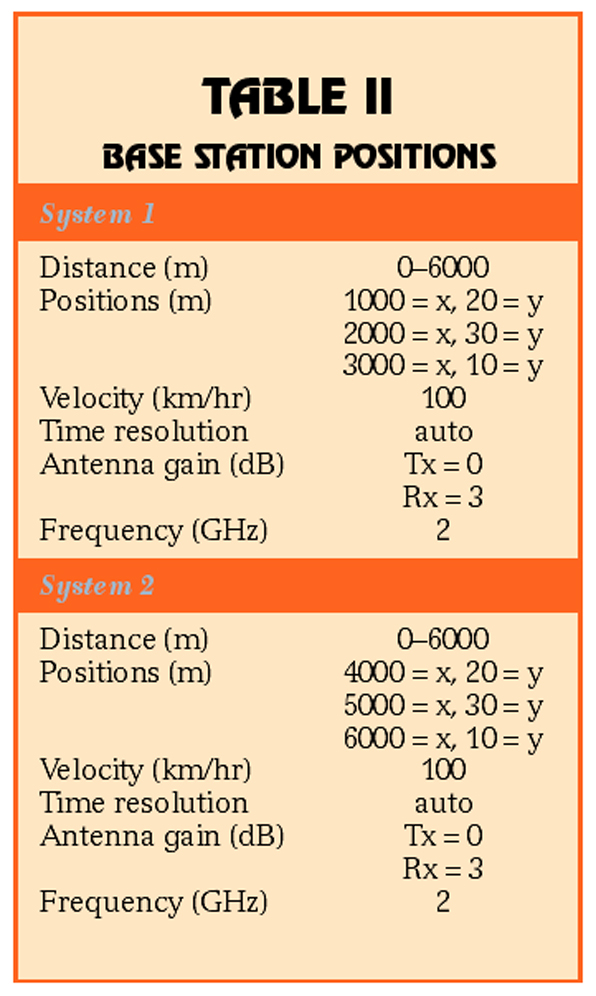
After the start command is issued the status line will trigger the second system to start the sequence. The operator can load the commands to each of the units with the proper test set-up information. An example of this is shown in Table 2. This will simulate six repeaters while the mobile is moving from 0 to 6000 meters at 100 km/hr.
Aeroflex/Weinschel Inc.
Frederick, MD
(800) 638-2048, (301) 846-9222,
www.aeroflex-weinschel.com
RS No. 301