
This is a survey article summarizing the recent developments and future trends in passive, active, bipolar and monolithic microwave integrated circuitry (MMIC) phased arrays for ground, ship, air and space applications. Covered is the DD(X) ship radar suite; THAAD (formerly GBR); European COBRA; Israel BMD radar antennas; Dutch shipboard APAR; airborne US F-22, JSF and F-18 radars, European AMSAR, Swedish AESA, Japan FSX and Israel Phalcon; Iridium (66 satellites in orbit for a total of 198 antennas) and Globalstar MMIC space-borne active array systems (these last two are for communications, but the technology is the same as used by radar systems. In fact, the IRIDIUM T/R module technology derives from technology developed for a space-based radar); Thales (formerly Thomson-CSF) 4" MMIC wafer, 94 GHz seeker antenna; digital beamforming; ferroelectric row-column scanning; optical electronic scanning for communications and radar; the MMIC C- to Ku-band advanced shared aperture program (ASAP) and AMRFS antenna systems for shared use for communications, radar, electronics countermeasures (ECM) and electronic support measures (ESM); and the continuous transverse stub (CTS) voltage-variable dielectric (VVD) antenna.
Accomplishments Over the Last Two and a Half Decades
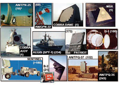
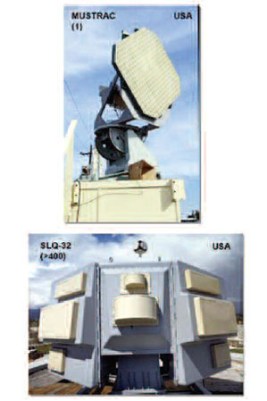
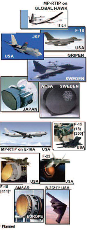
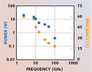
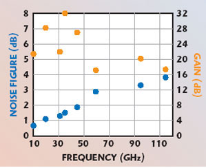
Phased arrays have come a long way in the last three decades. This is illustrated by the many tube passive arrays and solid-state active arrays, which use discrete and MMIC technologies that have been deployed or are under development.1–24,82–84,86 Figures 1 and 2 show passive phased arrays, the first generation of phased arrays. Figure 3 shows Rotman lens arrays. Figure 4 shows active solid-state arrays using discrete components, the second generation. Figures 5 and 6 are for phased arrays using microwave analog integrated circuits (MMIC), the third generation. The numbers manufactured are shown in parentheses in the figures. Note that in some cases, very large numbers have been produced, even for MMIC active phased arrays (see Table 1). Also, one sees that phased arrays are being developed around the world. Included are the new L-band GEC-Marconi S185OM (SMARTELLO), which will provide very long range search for the SAMPSON radar on the Royal Navy Type 45 anti-air warfare (AAW) destroyer and the new AMS L-band RAT 31DL.86 The SMARTELLO uses the SMART-L antenna and elements of the Martello. The Iridium satellite system has been deployed; it consists of a constellation of 66 satellites. It was a great technological success but unfortunately not a financial one.14 It is still in operation, however. In fact, three replacement satellites were launched in 2002. Figure 7 shows additional phased arrays that have recently come under development, for which the technology is not specified. Included are the US Army’s joint land attack cruise missile defense elevated netted sensors system (JLENS), consisting of a long range 3-D surveillance radar and a high frequency precision tracking and illumination radar deployed in an aerostat; the medium extended air defense system (MEADS) UHF surveillance radar; the US Army’s multi-mission radar (MMR); UK/US airborne stand-off radar (ASTOR), the UK equivalent of the US joint STARS (JSTARS), and the US Marine Corps affordable ground-based radar (AGBR) and multiple role radar system (MRRS). Figures 8 and 9 give the state-of-the-art of GaAs MMIC power amplifiers and of GaAs and InP low noise amplifiers (LNA).85 The People’s Republic of China has come a long way in a very short time in the development of phased arrays — passive, active, over-the-horizon, dual-band, wide-band, ultra-low sidelobe, synthetic-aperture, adaptive, digital-beamforming, super-resolution and phase only null steering.76 The question addressed now is what does the future hold?
Development of MMIC Active Phased Arrays
With the recent awards of production and development contracts for MMIC active phased array contracts, such as for three THAAD EDM (engineering development model) radars, COBRA radars, SAMPSON radars, sea-based test XBR radars, forward-based BMDs radars, MEADS radars, air traffic navigation, integration and coordination system (ATNAVICS) radars, four-faced active phased-array radar (APAR) system, the new B-2 radar, multi-platform radar technology insertion program (MP-RTIP) on E-10A (upgrade of the Joint STARS), MP-RTP on Global Hawk, F-15C (AN/APG-63(V), 25 already in service), F-16, F/A-18, F/A-22 and F-35 joint strike fighter (JSF) airborne radars, the planned development contracts for the new US DD(X) ship and SPY-3/VSR radar suite, the future looks very good for MMIC radars.79,80,83 The new X-band SPY-3 under development for the DD(X) ship, the US Navy’s first active radar, is planned to be used for the detection, tracking and illumination of low flying, anti-ship, cruise missiles and is expected to consist of a three-faced radar.83 When not supporting engagement operations, it will perform horizon search, surface search and periscope detection.83 The cooperative engagement capability (CEC) is a Navy ship and communications array antenna. Figures 10 and 11 show space-based radar and digital beamforming phased-array systems that have been deployed or are under development.
Research and Development Work for Future Phased-Array Systems
Clutter Rejection for an Airborne System (STAP and DPCA)
To cope with ground clutter and sidelobe jamming for airborne radar, extensive work is ongoing toward the development of an airborne phased array using space-time adaptive processing (STAP).25,26 STAP is a general form of displaced phase center antenna (DPCA) processing. STAP had been demonstrated several years ago on a modified E2-C system by NRL.27,28 More recently, a flight demonstration STAP provided 52 to 69 dB of sidelobe clutter cancellation relative to the main beam clutter.29 This system used an array mounted on the side of an aircraft. The antenna had 11 degrees of freedom in azimuth and two in elevation, for a total of 22. Before STAP, the antenna RMS sidelobe level was -30 dBi; with STAP, it was –45 dBi.
C- to Ku-band Multi-user Advanced Shared Aperture Program (ASAP) MMIC Array and Dual-band AMRFS and RECAP Arrays
The COBRA DANE radar system has a 16 percent bandwidth and the Rotman lens multi-beam array systems have a 2.5 to 1 frequency bandwidth. Technology had been carried out to develop an active MMIC phase-phase steered array that has a greater than 2 to 1 frequency bandwidth and at the same time is shared by multiple users. Specifically, the Naval Air Weapons Center (NAWC) and Texas Instruments (TI, now part of Raytheon) were developing a broadband array having continuous coverage from C- through Ku-band that would share the functions of radar, passive electronic support measures (ESM), active electronic counter measures (ECM) and communications.30 To achieve this wide bandwidth, a flared notch-radiating element was used. Cross notches were used so that horizontal, vertical or circular polarization could be obtained. They built a solid-state T/R module that provides coverage over this wide band from C- to Ku-band continuously. The module had a power output of 2 to 4 W per element, a noise figure between 6.5 and 9 dB, and power efficiency between 5.5 and 10 percent, over the band. A 10 by 10-element array, having eight active T/R modules, was built for test purposes. A typical full-up array would be approximately 29" wide by 13" high. With this type of array, it would be ultimately possible to use simultaneously part of the array as radar, part of the array for ESM, part for ECM and part for communications. The parts used for each function would change dynamically, depending on the need. Also, these parts could be non-overlapping or overlapping, depending on the needs. Although the ASAP funding has ended, the shared aperture technology is now being pushed forward by the US Office of Naval Research (ONR) advanced multifunction radar frequency system (AMRFS) program71,78 and the DARPA reconfigurable aperture program [RECAP] program. DERA of the UK had been developing a dual frequency array which would enable a single radar to use L-band for search and X-band for track, so as to avoid the use of a single compromise frequency for search and track.52 Consideration is being given to the use of waveguide L-band radiating elements and dipole X-band elements.
Digital Beamforming and Its Potential
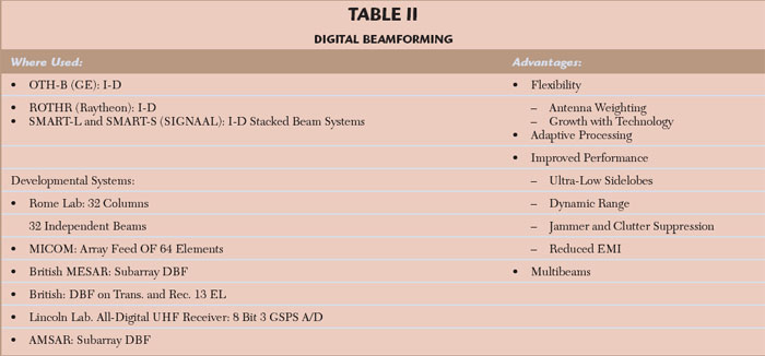
Table 2 lists where digital beamforming (DBF) has been operationally used, some developmental systems that have been built, and its significant advantages. The first operational radars to use digital beamforming are the over-the-horizon (OTH) radars, specifically the GE OTH-B and Raytheon relocatable OTH radar (ROTHR). The ROTHR receive antenna is approximately 8500 feet long. More recently, Signaal used digital beamforming for their deployed 3-D stacked beam SMART-L and SMART-S shipboard systems. Each row is down converted and pulse compressed with SAW lines and then analog-to-digital (A/D) converted with 12-bit, 20 MHz Analog Devices A/Ds. The signal is then modulated onto an optical signal and passed down through a fiber optic rotary joint to a digital beamformer where 14 beams are formed.31
A number of experimental DBF systems have been developed. One is the Rome Laboratory (Hanscom AFB, MA), 32 column linear array at C-band that can form 32 independent beams and uses a novel self-calibration system.32 Rome Laboratories has also developed a fast digital beamformer that utilizes a systolic processor architecture77 based on the quadratic residue number system (QRNS).32 MICOM (US Army) built a 64-element feed that used DBF for a space-fed lens.33 The experimental British MESAR S-band system does digital beamforming at the sub-array level.34 This experimental system has 16 sub-arrays and a total of 918 waveguide-radiating elements and 156 T/R solid-state modules. Roke Manor Research Ltd. of Britain has built an experimental 13-element array using digital beamforming on transmit as well as on receive.35 This experimental system uses the Plessey SP2002 chip running at a 400 MHz rate as a digital waveform generator at every element. Doing digital beamforming on transmit allows one to put nulls in the direction of an ARM threat or where there is high clutter.

The National Defense Research Establishment of Sweden has built an experimental S-band antenna operating between 2.8 and 3.3 GHz, which does digital beamforming using a sampling rate of 25.8 MHz on a 19.35 MHz IF signal.23 The advantage of using IF frequency sampling rather than base band sampling is that one does not have to worry about the imbalance between the two I and Q channels, or the DC offset. They demonstrated that, by using digital beamforming, they could compensate for amplitude and phase variations that occur from element to element, across angle and across the frequency band. Via a calibration, they were able to reduce an element-to-element gain variation over angle, due to mutual coupling, from ±1 dB to approximately ±0.1 dB. Using equalization, they were also able to reduce a ±0.5 dB variation in the gain over the 5 MHz bandwidth to less than ±0.05 dB. With this calibration and equalization, they were able to demonstrate peak sidelobes 47 dB down, over a 5 MHz bandwidth. A 50 dB Chebyshev weighting was used. The RMS of the error sidelobes was down 65 dB from the peak near boresight.63 They demonstrated that the calibration was maintained fairly well over a period of two weeks. This work demonstrates the potential advantage offered by digital beamforming with respect to obtaining ultra-low antenna sidelobes. These results were not achieved in real time in the field, although that is ultimately the goal.
MIT Lincoln Laboratory developed the technology for an all-digital radar receiver for airborne surveillance array radar like that of the UHF E-2C.43 They are A/D sampling directly at UHF (~430 MHz) using a Rockwell 8-bit, 3 Gbps A/D running at room temperature. Three stages of down conversion are done digitally and because the A/D quantization noise is filtered, the effective number of bits of the A/D is increased. For example, if the signal bandwidth is only 5 MHz, the increase in signal-to-noise ratio is 3 GHz/2 (5 MHz) = 25 dB, so the increase in the number of effective bits is 25 dB divided by 6 dB/bit or 4.2 bits to yield 12 bits total. The whole digital receiver is on an 8" by 8" card that uses three 0.6 mm chips. In the future these three chips could be replaced by a single 0.35 mm CMOS chip.
The Naval Research Laboratory (NRL), MIT Lincoln Laboratory and NSWC are jointly developing an L-band active array which has an A/D converter at every element.64,65,81 Using digital beamforming, NRL demonstrated the ability to obtain a constrained beamwidth with frequency, while at the same time achieving low sidelobes over specified angles and frequency bands.66
MIT Lincoln Laboratory had been developing a high performance, low power signal processor to do digital beamforming and signal processing for a notional X-band Discoverer II space-based radar.67,68 This notional version of the system did ground moving target indication (GMTI) and synthetic aperture radar (SAR) mapping. Its antenna consisted of 12 sub-arrays and 4 SLCs. The signal bandwidth was assumed to be 180 MHz. For this system, it is necessary to do the signal processing on-board and in real time, because telemetering the signal down would require too high a data rate –35 Gbps, if a 12-bit A/D is assumed — well beyond the present state-of-the-art. The on-board signal processor must do digital beamforming, pulse compression, Doppler processing, STAP and SLC. To do this on-board and in real time requires a signal processor capable of 1100 GOPS (1.1 TERAOP). Lincoln Laboratory has shown that it is feasible to do the processing on board using a systolic array type architecture having a volume less than one seventh of a cubic foot, and weighing less than 13 kg with a power consumption less than 55 W. With the digital processing field being moved forward rapidly by the commercial world, by the year 2016 it is expected that one 9U 16" by 14.5" board would provide a throughput of 600 GFLOPS (floating OPS). It would consist of 64 chips, each providing 10 GFLOPS use a 0.07 mm technology and have a 1.25 GHz clock. Texas Instruments (TI) road map, for its TMS320 digital signal processor (DSP), indicates that by the year 2010 they expect to be able to do 3 trillion, 8-bit OPS (3 trillion instructions per second or 3 TIPS), on a single TMS320 chip.69 With 32-bit fixed-point operations, this chip would do 0.75 TIPS. Assuming 10 percent efficiency, 15 chips would do the notional Discover II processing. Such processing capability could help make the experimental Swedish ultra-low sidelobe antenna and airborne STAP array feasible.
Row-column Steered Arrays
The Naval Research Laboratory (NRL) had been developing two row-column array steering techniques, which have the potential for low cost two-dimensional steered arrays.36,37 The first technique, the one closest to possible deployment, involves using two arrays back-to-back. The first array steers the beam in azimuth, the second in elevation. The first array consists of columns of slotted waveguides, with each column having at its input one ferrite phase shifter to provide azimuth scanning. The second array is a RADANT lens array, consisting of parallel horizontal conducting plates between which are connected many diodes. The velocity of propagation of the electromagnetic signal passing through a pair of parallel plates of the array depends on the number of diodes that are on or off in the direction of propagation. By appropriately varying this number, as one goes from one pair of plates to the next in the vertical direction, one creates a gradient on the signal leaving the lens in the vertical direction so as to steer the beam in elevation. The estimated production cost of the hybrid row-column steered array is $3 million. It is possible to use two RADANT lenses to provide two-dimensional electronic scanning, one RADANT lens providing elevation scan while the second provides azimuth scan.38 Thales has developed such a RADANT antenna for the Dassault Aviation RAFALE multi-role combat aircraft.38
The second NRL row-column steered array involves using two ferroelectric lenses.37 The first lens consists of columns of ferroelectric material placed between conducting plates. A DC voltage is applied across each pair of plates. The dielectric constant of the ferroelectric material depends on the DC voltage applied between the plates. As a result the phase of the electromagnetic signal passing through a ferroelectric column will depend on this DC voltage. Consequently, by applying an appropriate DC voltage across the ferroelectric columns, one can create a phase gradient in the horizontal direction for the signal leaving the first lens and thus scan the beam in azimuth. A second such lens, rotated 90°, would steer the beam in elevation. Considerable work is still necessary before a practical ferroelectric phased array is produced. This work has been shifted from NRL to industry.
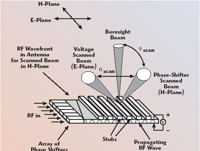
The Raytheon Co. is developing a row-column steered array that employs phase shifters for steering in the H plane (see Figure 12) and a voltage variable dielectric (VVD) ceramic material used for a continuous transverse stub (CTS) antenna architecture for steering in the E plane.41 Changing the voltage across the VVD changes its dielectric constant and, in turn, the velocity of propagation along the VVD. It provides for a lightweight, low cost, small thickness antenna. They are looking to apply this technology to aircraft radar antennas and commercial antennas. Engineers and scientists have been talking about achieving electronic scanning of lasers since the 1960s. Some thought this was a pipe dream, but these doubters have since been proven wrong. Raytheon40,57 has demonstrated an electronically steered phased array for laser and optical beams. This array, which is carried around in a briefcase, represents a major breakthrough in the scanning of laser and optical beams. The scanning is achieved using a row-column scanning architecture similar to that of the ferroelectric scanner previously described, with liquid crystal used instead of the ferroelectric material. In production, the cost per phase shifter for an optical phased array is estimated to be pennies.40,57
Novel Electronically Steerable Plasma Mirror
NRL had been pursuing the development of a novel electronically steerable plasma mirror in order to provide electronic beam steering.39 Here, a plasma sheet is rotated to steer the beam in azimuth and is electronically tilted to steer the beam in elevation. Switching to different initiation points in the cathode rotates the plasma mirror. Tilting the magnetic field around the plasma tilts the plasma mirror. This is done using coils placed around the plasma. These coils are placed so as not to block the microwave signal. A 50 by 60 cm plasma mirror has been generated, for which the measured antenna patterns had sidelobes approximately 20 dB down.39

95 GHz Reflect-array Using 4" MMIC Wafers
Colin38 described a very aggressive effort wherein an MMIC was taken to the point of wafer integration — 4" wafers. Specifically, Thales has built an experimental missile seeker antenna, which uses two 4" wafers.38 One wafer has the dipole elements and one bit PIN diode phase shifters printed on it. The second 4" wafer contains the driving circuits that are linked to the first through bumps. The antenna has 3000 elements. The beam width is 2° and can be steered ±45°. They have reported having obtained low sidelobes.38
Micro-electro-mechanical System (MEMS) Components
The MEMS integrated circuit mechanical switch holds the promise for a 4-bit X-band phase shifter having low loss (1.5 dB), low power consumption (1 mW) and low cost ($10 per phase shifter).70 If such a phase shifter bears fruit, it would be possible to revert back for some applications to the passive phase-phase scanned array architecture having one power amplifier feeding many low cost phase shifters. Instead of a tube, the power amplifier could be a solid-state amplifier. This could reduce the number of T/R modules needed and hence the cost of a phase-phase scanned array by a considerable amount. The MEMS technology is being funded by DARPA.70 They are looking at using MEMS in their RECAP program to obtain reconfigurable ultra-wideband antennas for multi-user applications as done with the ASAP program described above.74,75
Low Cost Phase Array for the Automobile
One tends to think of phased arrays as expensive. A low cost 77 GHz phased array has been developed for automotive intelligent cruise control radar, whose total consumer cost needs to be less than $300.72,73 Two antennas, one for transmit and one for receive, and their beamformer networks are photo-etched on a single sheet of copper clad dielectric. The antennas consist of series fed columns of patch radiators, while the beam-formers are Rotman lens, one for each array. The beams are scanned in azimuth by switching between input ports of the Rotman lens.
Conclusion
Based on the above accomplishments, ongoing developments, research and large numbers of programs that are looking to effectively use phased arrays, it is apparent that the future for phased arrays is very promising and should lead to exciting developments. Phased arrays have come a long way and can be expected to make major strides in the future. For further reading on recent developments in phased arrays around the world, the reader is referred to References 1 to 14, 40, 46, 62, 82 and 83.
Acknowledgment
The author would like to thank Doug Venture of the Raytheon Co. for his help.
References
1. E. Brookner, “Phased Arrays for the New Millennium,” Proceedings of the IEEE 2000 International Symposium on Phased Array Systems and Technology, Dana Point, CA, May 2000, pp. 3-19.
2. E. Brookner, “Phased Arrays–Major Advances and Future Trends Into The Next Millennium,” Proceedings of the 28th Moscow International Conference on Antenna Theory and Technology, Moscow, Russia, September 1998, pp. 24-42.
3. E. Brookner, "Phased-array Radars," Scientific American, February 1985, pp. 94-102.
4. E. Brookner (Ed.), Practical Phased Array Antenna Systems, LexBook, Lexington, MA (formerly published by Artech House), 1991.
5. E. Brookner, Aspects of Modern Radar, Ch. 2, LexBook, Lexington, MA (formerly published by Artech House), 1988.
6. E. Brookner, Radar Technology, LexBook, Lexington, MA (formerly published by Artech House), 1977.
7. J. Rhea, "Active Array Antennas Head for the Sky's," Military and Aerospace Electronics, August 1996.
8. E. Brookner, "Radar Imaging for Arms Control," Ch. 11 in Arms Control Verifications, The Technologies That Make It Possible, K. Tsipis, D.W. Hafemeister and P. Janeway (Ed.), Pergamon-Brassey's, London, 1986.
9. E. Brookner, "Large Phased-array Radars", Ch. 7 in Nuclear Arms Technologies in the 1990s, D. Schroeer and D. Hafemeister (Ed.), American Institute of Physics, New York, 1988.
10. M. Sarcione, J. Mulcahey, D. Schmidt, K. Chang, M. Russell, R. Enzmann, P. Rawlinson, W. Gluzak, R. Howard and M. Mitchell, "The Design, Development and Testing of the THAAD (Theater High Altitude Area Defense) Solid State Phased Array (formerly Ground Based Radar)," Proceedings of the IEEE 1996 International Symposium on Phased Array Systems and Technology, Boston, MA, October 1996, pp. 260-265.
11. E.D. Cohen, "Trends in the Development of MMICs and Packages for Active Electronically Scanned Arrays (AESA)," Proceedings of the IEEE 1996 International Symposium on Phased Arrays Systems and Technology, Boston, MA, October 1996, pp. 1-4.
12. D. Archer, "Lens-fed Multiple Beam Arrays," Electronic Progress, Vol. 16, No. 4, Winter 1974, pp. 24-32 or D. Archer, "Lens- Fed Multiple-Beam Arrays," Microwave Journal, Vol. 18, No. 10, October 1975, pp. 37-42.
13. A. Black, "Multibeam Systems," Electronic Progress, Vol. 17, No. 3, Fall 1975, pp. 32-42.
14. J.J. Schuss, J. Upton, B. Myers, T. Sekina, A. Rohwer, P. Makridakas, R. Francois, L. Wardle, W. Kreutel and R. Smith, "The IRIDIUM Main Mission Antenna Concept," Proceedings of the IEEE 1996 International Symposium on Phased Array Systems and Technology, Boston, MA, October 1996, pp. 411-415.
15. E. Brookner and T.S. Mahoney, "Derivation of a Satellite Radar Architecture for Air Surveillance," Microwave Journal, Vol. 29, No. 2, February 1986, pp. 173-191. See also M.I. Skolnik (Ed.), Radar Applications, IEEE Press, New York, 1988.
16. A. Farina, Antenna-Based Signal Processing Techniques for Radar Systems, Artech House, 1992.
17. R. Nitzberg, Adaptive Signal Processing for Radar, Artech House, 1992.
18. E. Brookner, "Sidelobe Cancellation" and "Adaptive Arrays,” The Institution of Electrical Engineers (IEE) Tutorial Seminar on "Adaptive Radar Processing," London, England, October 1987, pp. 1-74.
19. E. Brookner, "Ubiquitous Orthonormal Transformation in Sidelobe Canceling, Adaptive Arrays and Tracking," Proceedings of the IEEE Long Island Section, Adaptive Antenna Systems Symposium, November 1992, pp. 23-30.

20. J.R. Johnson, F.G. Willworth, H.M. Aumann and A.J. Fenn, “Receiver Channel Equalization for Adaptive Antennas: Experimental Results,” 1990 International Antennas and Propagation Symposium Digest, pp. 194-197.
21. A.J. Fenn, H.M. Aumann, F.G. Willwerth and J.R. Johnson, “Focused Near-Field Adaptive Nulling: Experimental Investigation, 1990 International Antennas and propagation Symposium Digest, pp. 186-189.
22. B.D. Carlson, L.M. Goodman, J. Austin, M.W. Gantz and L.O. Upton, “An Ultralow-sidelobe Adaptive Array Antenna,” The Lincoln Laboratory Jour, Summer 1990, pp. 291-310.
23. L. Pettersson, M. Danestig and U. Sjostrom, "An Experimental S-band Digital Beamforming Antenna," Proceedings of the IEEE 1996 International Symposium on Phased Array Systems and Technology, Boston, MA, October 1996, pp. 93-98.
24. E. Brookner and J.M. Howell, "Adaptive-array Processing," Phased Arrays Symposium Proceedings, The Mitre Corp., Bedford, MA, October 1985, pp. 133-146. See also: RADC Rep. No. RADC-TR-85-171, Electromagnetics Science Division, RADC, Hanscom AFB, Bedford, MA, AF Systems Command, August 1985; IEE International Conference Radar, London, England, October 1987; Proceedings of the IEEE, Vol. 74, No. 4, April 1986, pp. 602-604.
25. L.E. Brennan, J.D. Mallett and I.S. Reed, "Adaptive Arrays in Airborne MTI Radar," IEEE Transactions on Antennas and Propagation, Vol. 24, No. 5, September 1976, pp. 607-615.
26. J. Ward, Space-time Adaptive Processing for Airborne Radar, MIT Lincoln Laboratory, Technical Report 1015, December 1994.
27. F.W. Lee and F. Staudaher, "The NRL Adaptive Array Flight Test Database," Proceedings of the IEEE Long Island Section Adaptive Antenna Systems Symposium, November 1992, pp. 101-104.
28. L.E. Brennan, D.J. Piwinski and F.M. Staudaher, "Comparison of Space-time Adaptive Processing Approaches Using Experimental Airborne Radar Data,” The Record of the 1993 IEEE National Radar Conference, Lynnfield, MA, April 1993, pp. 176-181.
29. D.K. Fenner and W.F. Hoover, Jr., "Test Results of a Space-time Adaptive Processing System for Airborne Early Warning Radar," IEEE 1996 National Radar Conference, May 1996, Ann Arbor, MI.
30. C. Hemmi, R.T. Dover, A. Vespa and M. Fenton, "Advanced Shared Aperture Program (ASAP) Array Design," Proceedings of the IEEE 1996 International Symposium on Phased Array Systems and Technology, Boston, MA, October 1996, pp. 278-282.
31. I.W.T.A. de Heig and I.H.T. Muskens, "Multi-channel Receiver and Optical Data Link for Radar Systems with Digital Beamforming," The Record of the IEEE 1995 International Radar Conference, Alexandria, VA, May 1995, pp. 201-206.
32. H. Steyskal, "Digital Beamforming at Rome Laboratory," The Rome Laboratory Technical Journal, Vol. 1, No. 1, June 1995, pp. 7-22.
33. J.F. Rose, B.A. Worley and M.M. Lee, “Antenna Patterns for Prototype Two-dimensional Digital Beamforming Array,” IEEE Antennas and Propagation International Symposium, University of Michigan, Ann Arbor, MI, June 1993, pp. 1544-1547.
34. E.R. Billam and D.H. Harvey, "MESAR-An Advanced Experimental Phased Array Radar," IEEE International Conference on Radar, October 1987, pp. 37-40.
35. A. Garrod, "Digital Modules for Phased Array Radar," IEEE International Symposium on Phased Array Systems and Technology, Boston, MA, October 1996, pp. 81-86.
36. J.B.L. Rao, P.K. Hughes, III, G.V. Trunk and J.C. Sureau, "Affordable Phased-array for Ship Self-defense Engagement Radar" Proceedings of the 1996 IEEE National Radar Conference, Ann Arbor, MI, May 1996, pp. 32-37.
37. J.B.L. Rao, G.V. Trunk and D.P. Patel, "Two Low-cost Phased Arrays," Proceedings of the IEEE 1996 International Symposium on Phased Array Systems and Technology, Boston, MA, October 1996, pp. 119-124.
38. J.M. Colin, "Phased Array Radars in France: Present and Future," IEEE International Symposium on Phased Array Systems and Technology, Boston, MA, October 1996, pp. 458-462.
39. J. Mathew, R.A. Meger, J.A. Gregor, D.P. Murphy, R.E. Pechacek, R.F. Fernsler and W.M. Manheimer, "Electronically Steerable Plasma Mirror," Proceedings of the IEEE 1996 International Symposium on Phased Array Systems and Technology, Boston, MA, October 1996, pp. 58-62.
40. E. Brookner, "Major Advances in Phased Arrays: Part I," Microwave Journal, Vol. 40, No. 5, May 1997, pp. 288-294, "Major Advances in Phased Arrays: Part II," Microwave Journal, Vol. 40, No. 6, June 1997, pp. 84-92.
41. T.W. Bradley et al., "Development of a Voltage-variable Dielectric (VVD), Electronic Scan Antenna," IEE 1997 International Radar Conference, Edinburgh, Scotland, October 1997, pp. 383-385.
42. M.E. Russell, A. Crain, A. Curran, R.A. Campbell, C.A. Drubin and W.F. Miccioli, "Millimeter-wave Radar Sensor for Automotive Intelligent Cruise Control (ICC)," IEEE Transactions on Microwave Theory and Techniques, Vol. 45, No. 12, December 1997, pp. 2444-2453.
43. W.S. Song, "A New 3-GSPS 65-GOPS UHF Digital Radar Receiver and Its Performance Characteristics," 1997 ALISOMAR Conference.
44. B. Palumbo, "Some Examples of System Developments in Italy Based on Phased Array Technology," IEEE International Symposium on Phased Array Systems and Technology, Boston, MA, October 1996, pp. 444-449.
45. S. Dryer, E. Levine, M. Peleg and A. Schrift, "EL/M 2080 ATBM Early-warning and Fire-control Radar System," Proceedings of the IEEE 1996 International Symposium on Phased Array Systems and Technology, Boston, MA, October 1996, pp. 11-16.
46. E. Brookner, "Report on 1996 Phased Array Symposium," IEEE Antennas of Propagation Magazine, Vol. 39, February 1997, pp. 114-118.
47. G.J. Albarel, J.S. Tanner and M. Uhlmann, "AMSAR Antenna Architecture and Predicted Performance," Proceedings of the IEEE 1996 International Symposium on Phased Array Systems and Technology, Boston, MA, October 1996, pp. 450-453.
48. L. Josephson, L. Erhage and T. Emanuelsson, "An AESA Development Model for Next-generation Fighter Aircraft," Proceedings of the IEEE 1996 International Symposium on Phased Array Systems and Technology, Boston, MA, October 1996, pp. 454-457.
49. A.R. Moore, D.M. Salter and W.K. Stafford, "MESAR Multi-function, Electronically Scanned, Adaptive Radar," IEE 1997 International Radar Conference, Edinburgh, Scotland, October 1997, pp. 55-59.
50. A.B. Smolders, "Design and Construction of a Broadband Wide-scan Angle Phased-array Antenna with 4096 Radiating Elements," Proceedings of the IEEE 1996 International Symposium on Phased Array Systems and Technology, Boston, MA, October 1996, pp. 87-92.
51. D.A. Fulghum and J.C. Anselmo, "DARPA Pitches Small Sats for Tactical Reconnaissance," Aviation Week and Space Technology, June 1997, pp. 29-30.
52. S.A.W. Moore and G.A. Hockham, "Dual Frequency Multi-function Radar Antenna Research," IEE 1997 International Radar Conference, Edinburgh, Scotland, October 1997, pp. 50-54.
53. W. Gruener, J.P. Toernig and P.J. Fielding, "Active-Electronically-scanned-Array Based Radar System Features," IEE 1997 International Radar Conference, Edinburgh, Scotland, October 1997, pp. 339-343.
54. G. Albarel, J.S. Tanner and M. Uhlmann, "The Trinational AMSAR Programmer: CAR Active Antenna Architecture," IEE 1997 International Radar Conference, Edinburgh, Scotland, October 1997, pp. 344-347.
55. H.P. Feldle, A.D. McLachlan and Y. Mancuso, "Transmit/Receive Modules for X-band Airborne Radar," IEE 1997 International Radar Conference, Edinburgh, Scotland, October 1997, pp. 391-395.
56. E. Brookner, "Filtering and Kalman Filtering Made Easy, " Section 4.4: "Adaptive Nulling, the Orthonormal Transformation, and the LSE," John Wiley and Sons Inc., New York, NY, 1998, pp. 188-200.
57. T.A. Dorschner, L. Friedman, M. Holz, D.P. Resler, R.C. Sharp and I.W. Smith, "An Optical Phased Array for Lasers," Proceedings of the 1996 IEEE International Symposium of Phased Array Systems and Technology, October 1996, Boston, MA, pp. 5-10.
58. G.J. Albarel, J.S. Tanner and M. Uhlmann, “AMSAR Active Antenna Technology and First Measured Performance”, 5th International Conference and Exhibition on Radar Systems, Brest, France, May 1999, Session 2.2.
59. A.K. Golshayan, S.v.d. Schoot and P. vanGenderen, “Active Phased Array Radar (APAR),” 5th International Conference and Exhibition on Radar Systems, Brest, France, May 1999, Session 1.5.
60. R. Scott, “PAAMS Deal Switches SAMPSON to Active Mode”, Janes Defense Weekly, December 15, 1999.
61. C.F. Foss, “Long-Awaited Deal for COBRA Radar is Awarded”, Janes Defense Weekly, March 18, 1998.
62. Special Issue on Phased Arrays of IEEE Transactions on Antenna and Propagation, March 1999.
63. L. Pettersson, private communication, April 2000.
64. B.H. Cantrell, J.W. de Graaf and L.M. Leibowitz, "Digital Active-aperture Phased-array Radar," IEEE International Conference on Phased Array Systems and Technology, Dana Point, CA, May 2000.
65. G.W. Meurer, B. Cantrell and R. Stapleton, "Digital Array Technology for Radar Applications," IEEE 2000 International Radar Conference, Washington, DC, May 2000.
66. D.P. Scholnik and J.O. Coleman, "Optimal Design of Wideband Array Patterns," IEEE 2000 International Radar Conference, Washington, DC, May 2000.
67. W.S. Song, E.J. Baranoski and D.R. Martinez, "One Trillion Operations Per Second On-board VLSI Signal Processor for Discoverer II Space Radar," IEEE Aerospace Conference Proceedings, March 2000.
68. W.S. Song, M.M. Vai, H.T. Nguyen and A.H. Horst, "High-performance Low-power Polyphase Channelizer Chip Set," Signals, Systems and Computers, Conference Record of the Thirty-Fourth Asilomar Conference, Vol. 2, 2000.
69. Electronic Design, January 10, 2000.
70. J.K. Smith, F.W. Hopwood and K.A. Leahy, "MEM Switch Technology in Radar," IEEE 2000 International Radar Conference, pp. 193-198.
71. R. Holzer, “Integrated Radar Concept Anchors US Navy Vision,” Defense News, April 24, 2000, pp. 1, 44.
72. M. Russell, A. Crain, A. Curran, R. Campbell, C. Drubin and W. Miccioli, “Millimeter–wave Radar Sensor for Automotive Intelligent Cruise Control (ICC),” IEEE Transactions on Microwave Theory and Techniques, Vol. 45, December 1997, pp. 2444-2453.
73. M. Russell, C.A. Drubin, A.S. Marinilli, W.G. Woodington and M.J. Del Checcolo, “Commercial Radar Technology,” IEEE 2000 International Radar Conference, pp. 819-824.
74. W. Weedon, W. Payne and G. Rebeiz, “MEMS-switched Reconfigurable Antennas,” Proceedings of the IEEE 2001 Antennas and Propagation Society International Symposium, Vol. 3, pp. 654-657.
75. J. Schaffner, D. Sievenpiper, R. Loo, J. Lee and S. Livingston, “A Wideband Beam Switching Antenna Using RF MEMS Switches,” Proceedings of the IEEE 2001 Antennas and Propagation Society International Symposium, Vol. 3, pp. 658-661.
76. W.X. Zhang, “Antenna Development in China,” IEEE Antennas and Propagation Magazine, Vol. 38, No. 6, December 1996, pp. 49-63.
77. E. Brookner, "Tracking and the Kalman Filter Made Easy", John Wiley & Sons Inc., New York, NY, 1988.
78. P.K. Hughes and J.Y. Choe, “Overview of Advanced Multifunction RF Systems (AMRFS),” Proceedings of the IEEE International Conference on Phased Array Systems and Technology, Dana Point, CA, May 2000, pp. 21-24.
79. G.H.C. Van Werkhoven and A.K. Golshayan, “Calibration Aspects of the APAR Antenna Unit,” Proceedings of the IEEE 2000 International Conference on Phased Array Systems and Technology, Dana Point, CA, May 2000, pp. 425-428.
80. A.K. Agrawal, B.A. Kopp, M.H. Luesse and K.W. O’Haver, “Active Phased Array Antenna Development for Modern Shipboard Radar Systems,” Johns Hopkins APL Technical Digest, Vol. 22, No. 4, 2001, pp. 600-612.
81. B. Cantrell, J. de Graaf, F. Willwerth, G. Meurer, L. Leibowitz, C. Parris and R. Stapleton, “Development of a Digital Array Radar (DAR),” IEEE AESS Magazine, March 2002, pp. 22-27.
82. C.A. Fowler, “Old Radar Types Never Die,” IEEE AESS Magazine, September 1998.
83. W.L. Fontana and K.H. Krueger, “AN/SPY-3: The Navy’s Next–generation Force Protection Radar System,” Proceedings of the IEEE 2003 International Symposium on Phased Array Systems and Technology, Boston, MA, October 2003; also published in Navy Surface Warfare Center, Dahlgren Division Technical Digest, 2000-2001 Issues: Theater Air Defense, pp. 230-239.
84. Proceedings of the IEEE 1996, 2000 and 2003 International Symposiums on Phased Array Systems and Technology held respectively in Boston, MA, October 1996, Dana Point, CA, May 2000, and Boston, MA, October 2003.
85. Courtesy of Colin Whelan of the Raytheon Co.
86. M. Cicolani, A. Farina, E. Giaccari, F. Madia, R. Ronconi and S. Sabatini, “Some Phased Array Systems and Technologies in AMS,” IEEE 2003 International Symposium on Phased Array Systems and Technology, Boston, MA, October 2003.