
This standard is usually used in conjunction with a product standard that will specify this and other test standards, detailing the requirements the product must meet. The product standard may give additional guidance on how this test standard is used, including test level severity and changes to procedure.
The object of this standard is to establish a common reference for immunity to radio frequency (RF) radiation caused by any source. Electronic products need to be designed and tested to have immunity from these sources. RF radiation can come from many sources such as other electronic devices, electric motors and intentional transmitters such as walkie-talkies and cell phones. The introduction of more wireless devices in the past couple of years has increased the need for this testing, not only to satisfy governmental requirements, but also to increase product reliability, which increases customer satisfaction.
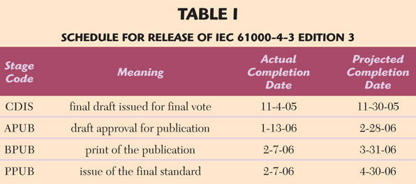
Note: This document should not be used in conjunction with or instead of the official released publication. It is only intended to provide guidance and information on the possible changes. One should always refer to the latest standards: IEC 61000-4-3: Electromagnetic compatibility (EMC)—Part 4-3: Testing and measurement techniques—Radiated, radio frequency, electromagnetic field immunity test. Edition 3 has been approved and released ahead of schedule. Table 1 shows the current status.
Major Changes in IEC 61000-4-3 Edition 3
The major changes to IEC 61000-4-3 Edition 3 include:
• New harmonic distortion requirement for the test setup: better than 6 dBc.
• New linearity check to make sure the RF amplifier is not operating in compression.
• New extension of the frequency range up to 6 GHz.
• New test table material requirement.
These changes could have a big effect on some facilities and test equipment.
Harmonic Distortion
Harmonic distortion is the level difference in decibels between the fundamental frequency and its harmonics. The new standard calls for a harmonic distortion of better than –6 dBc for the test setup. This means that all harmonics must be 6 dB below the fundamental out of the transmitting antenna, which could become a problem when using RF amplifiers in compression or when using traveling wave tube (TWT) amplifiers. TWT amplifiers have been used historically for testing above 1 GHz when high power is required and can offer significant cost/performance benefits at very high power levels.
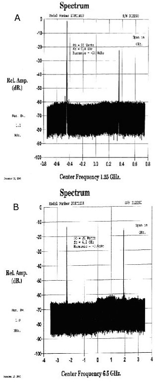
Since the introduction of solid-state amplifiers in this frequency range, many of the limitations of TWT amplifiers have been overcome and, at lower power levels, solid-state amplifiers are readily available. TWT amplifiers can still be used for high power testing, but care must be taken to satisfy the standard. Some TWT amplifiers include methods for harmonic reduction by combining tubes or switching-in filters. For most other TWT amplifiers, RF filters can be attached externally to block these unwanted harmonics. Figure 1 shows an example of the harmonic content of a solid-state and a TWT amplifier (each rated 20 W).
The solid-state amplifier has an excellent harmonic level of –24 dBc while the TWT amplifier’s level is only –0.8 dBc. The harmonic of the TWT will contribute to the calibration level since a broadband RF field probe is used and cannot distinguish between a desired and unwanted signal. In addition, the antenna gain usually increases over its operating band. The antenna gain can be as much as 5 dB higher at the harmonic frequency. In the above case, the –0.8 dBc harmonic distortion of the TWT will result in a much higher field level at the harmonic than at the fundamental.
These harmonics will result in a significant error in field level and RF filters will be required. The consequence of using filters will be some loss in power and loss of productivity while switching these filters in and out. The amplifier used will dictate what frequency range(s) the filter will need to cover, or if multiple filters will be needed. The solid-state amplifier will not need filtering for this reason. High harmonic content can also have an unwanted adverse effect on the equipment under test (EUT).
The harmonic could be at a frequency that causes the EUT to fail. Since the test personnel are testing at the fundamental frequency, they will mark this frequency as the failure, which is not the case. It is quite possible that this harmonic may be outside the intended test frequency range and therefore should not even be part of the test. From the EUT manufacturer’s point of view, harmonics are very much unwanted since this signal can cause failures and is not part of the test.
If one works backwards, an acceptable amplifier harmonic content rating can be estimated:
Maximum antenna gain between harmonic and fundamental = 5 dB
Other effects from setup and room (safety factor) = 3 dB
Required by specification = 6 dB
Total = 14 dB
Therefore, a harmonic content for the amplifiers better than –14 dBc will be more than acceptable. This would be a more than safe harmonic content requirement for the amplifier, guaranteeing an acceptable harmonic level during testing.
Note: The amplifier should not be operated into compression and filters can be used to reach this requirement.
Linearity Check
The linear region of an amplifier is the power range in which there is a 1:1 ratio (in decibels) input change to output change. As the amplifier starts to saturate, this will no longer be true. AR’s solid-state amplifiers are specified at both 1 and 3 dB compression points. Below the 1 dB compression point, the amplifier’s response is referred to as linear. Above the 3 dB compression point, the amplifier is in full compression. There are two main reasons why this is important.
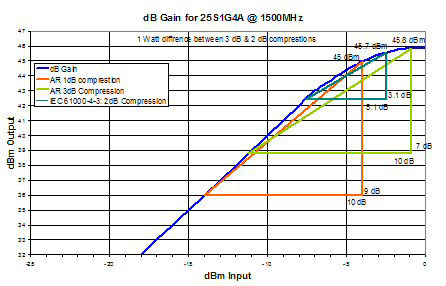
First, if amplifiers are being run while in compression, the output signal will be distorted. This means a sine wave will start to resemble a square wave. In the case of the IEC 61000-4-3, the amplitude modulation (AM) will also be distorted, possibly causing different unrepeatable test results. Second, when an amplifier is being run close to saturation, the harmonic content will increase. Figure 2 shows one of AR’s solid-state amplifiers and how AR finds its 1 and 3 dB compression points.
Basically, the point where an increase of 10 dB in input power results in only a 9 dB change of output power is the 1 dB compression point (orange triangle). The point where the input is increased by 10 dB results in only a 7 dB change on the output is the 3 dB compression point (green triangle).
The new specification calls for a check for a 2 dB compression point (yellow triangle), while connected to the antenna. If the load impedance (antenna) on the amplifier is a pure 50 Ω, then amplifier manufacturers could easily specify this new 2 dB compression point to be used as a reference when calculating one’s requirements. Since any antenna, which is used during testing is not a pure 50 Ω load, but an unknown complex load, the compression point may vary slightly.
For this reason, it is best to size amplifiers based on the manufacturer’s supplied 1 dB compression point to allow for some margin of error. This will be a concern when using a TWT amplifier since they are normally not as linear as solid-state amplifiers.
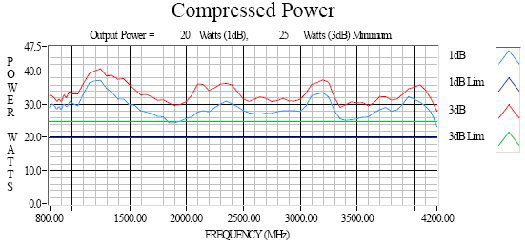
The 1 dB compression point is usually approximately 50 percent of its rated power; therefore, a 20 W TWT amplifier will have a 1 dB compression rating of approximately 10 W. In the case of a 25S1G4A solid-state amplifier, the minimum output power rating is 25 W with a minimum 1 dB compression rating at approximately 20 W. The actual production testing done on one of these 25S1G4A amplifiers at 1.5 GHz is shown in Figure 3.
The amplifier is actually rated at 38 W, with a 1 dB compression rating of approximately 30 W. It is always best to check the amplifier’s specification or to contact the manufacturer directly for this information and assistance with the selection of the product that will meet the requirements.
Increased Frequency Range
The frequency range increase from 2 to 6 GHz is directly in response to the use of more of the RF spectrum by the communication industries. In different countries and locations, the RF spectrum is being divided up depending on each country’s laws. Based on where the equipment under test (EUT) is being used, not all frequency bands may need to be tested. In addition, not all communication standards use the same signal strengths. This is why this new test standard is leaving this further definition up to forthcoming product standards. Product standards will specify what additional frequencies to cover in the communications bands: 800 to 960 MHz and 1.4 to 6.0 GHz. Product standards will also specify test levels that may not be consistent throughout the bands. The current 80 MHz to 1 GHz requirement should remain the same.
The test chamber setups may have to change because of this higher frequency requirement. Many laboratories have only a ferrite-lined chamber. This works well when testing at less than 1 GHz, but as the frequency rises it will become increasingly difficult to meet the field uniformity requirements. This is because the ferrite is not very absorbent above 1 GHz and will reflect the RF field. Annex C of IEC 61000-4-3 Edition 3 explains this situation and gives good advice and options on correcting this problem. A fully lined anechoic chamber with ferrite and absorber material will work fine.
Test Table
A low permeability material is now specified for the test table. Rigid polystyrene is one material that is suggested. In the past, many laboratories used wood, which is fine when testing at lower frequencies. Now that the test frequencies can be as high as 6 GHz, wood will start to have some unwanted properties. High frequencies will be reflected, making it difficult to meet the uniform field requirement. The reflections will also make test results less repeatable.
General Test Tips
The above new requirements could require laboratories to upgrade and purchase new equipment. Some helpful hints may increase the likelihood of success.
If harmonic content is an issue: RF filters on the amplifier’s output may fix the problem.
• Make sure the additional losses of the filters do not force the amplifier into saturation.
• Switching filters in and out will increase test time.
If working in saturation: Reduce all RF losses in the system.
• Use good low loss RF cables and connectors.
• Make sure all connections are tight.
• Make sure all connectors are clean.
• Shorten RF cables (may require the amplifier to be moved closer to the antenna).
• Use a different RF antenna.
• Higher gain antennas will require less power.
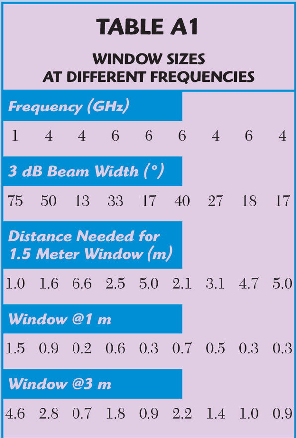
• Keep in mind that a narrow beam width may not cover the full window of 1.5 m x 1.5 m uniform field calibration requirement (See Appendix A for antenna coverage calculations). Calibration to a smaller window is allowed above 1 GHz.
• Horn antennas will direct the energy forward better than log antennas, resulting in better field performance.
• Move the antenna in closer, not less than 1 meter.
If the above considerations are taken into account and the requirements can still not be met, a new amplifier may be needed.
Conclusion
The increased frequency range of this standard has brought some common test problems to light as to their contribution to test error. Continuing efforts must be taken to maintain a consistently repeatable test. Both harmonic distortion and amplifier linearity are issues that, until now, have been overlooked by this standard. All RF amplifiers can run in compression and produce harmonics.
If the amplifier is running in compression and if the antenna and cables cannot be improved upon, a new higher power amplifier will be needed. If harmonic content becomes an issue, RF filters will be needed to block out these harmonics. With low noise solid-state amplifiers, filters will not be needed.
It is also a good idea to ask manufacturers for examples of test data taken from production units. This data can aid in product selection and give a better level of confidence of the manufacturer’s ability to meet their published specifications.
Quality of testing and repeatability should be the goal of every EMC test lab.
If repeatability was not important, then these international test standards would be useless. Once this IEC standard is published, there will be an overlap period before the previous standard is removed from use.
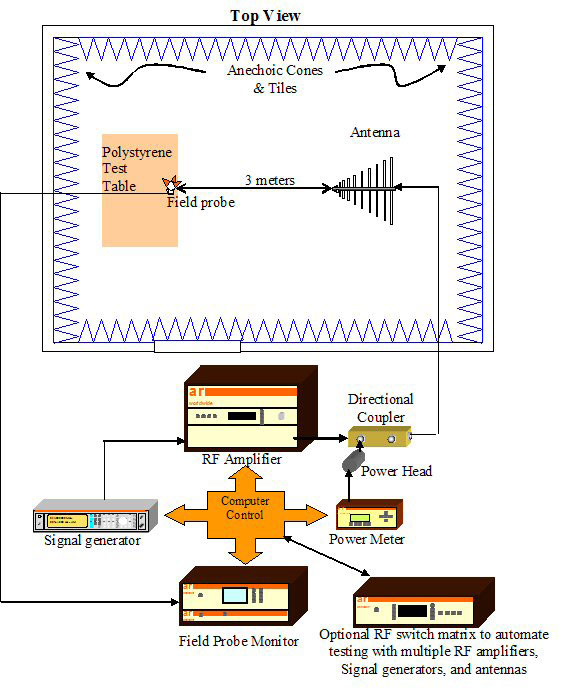
The main procedural changes will be harmonic distortion, linearity check and test table. Depending on the setup, the test setup may need to be changed and/or possibly new equipment purchased. Figure 4 shows the diagram of a typical radiation immunity test setup.
 Jason Smith earned his BS degree in engineering technology from the University of Delaware in 1997.
After college he started working for Candes Systems Inc., Harleysville, PA, as a computer specialist for TEMPEST computer systems. He was subsequently promoted to a test engineer position with its sister company Radiation Sciences Inc. and quickly became the EMC lab manager of the company’s independent EMC test house.
He moved on to work for Omega Engineering Inc. as the company’s EMC lab manager for its commercial EMC test lab, Analab Llc.
Smith has seven years of EMC testing experience with military, avionics, commercial, medical, telecom and automotive testing. He joined AR RF/Microwave Instrumentation in February 2004.
His current position is supervisor application engineering.
In this position he is product applications support to customers, technical training and technical writing, and provides guidance for product development for AR RF/Microwave Instrumentation’s full range of products.
APPENDIX A
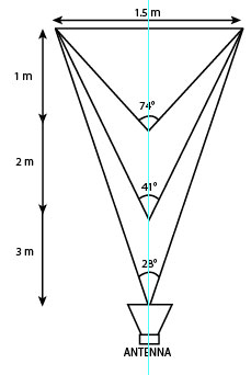
Using basic geometry, the window size (spot size) can be calculated from the 3 dB beam width of the antenna. (See Figure A1 and Table A1.)

where
Θ = 3 dB beam width of the antenna at the specified frequency
W = window width
D = antenna distance