

Digitally tunable bandpass filters are essential to modern SDR systems. They provide precise frequency control with hundreds of sub-MHz settings, low insertion loss (typically 5 to 7 dB across wide ranges), and excellent linearity (in-band IIP3 > 40 dBm). These filters can replace large, switched filter banks with a single chip.
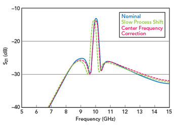
Fig 3 X-Band SOI tunable filter variation characteristics.
These filters are built using SOI technology, which enables precise control of their features at low cost. SOI offers benefits such as lower parasitic capacitance and higher-quality resonators. It also enables better separation between control and RF paths and strong linearity due to reduced substrate coupling. This results in tight process control, minimal temperature drift and consistent amplitude and phase across units. As a result, filters exhibit stable shapes, predictable delays and reliable rejection across channels, which is important for phased arrays and multi-channel SDRs, where mismatches can degrade performance.
When considering the impact of process variation, a few application scenarios are worth examining. In the first scenario, process shifts are small, causing only slight shifts in the filter’s center and its 3 dB frequency points. The 3 dB bandwidth itself, however, remains essentially constant and if it is wide enough to encompass the application’s required frequency range, the impact of process variation on filter performance is transparent to the end user, see Figure 3.
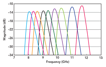
Fig 5. X-Band SOI Tunable Filter Narrowband Tuning Mode.
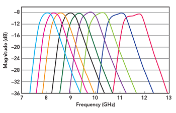
Fig 4. X-Band SOI Tunable Filter Wideband Tuning Mode.
In the second scenario, the process shift is large enough to push the filter’s 3 dB bandwidth outside the application’s required frequency range. In this case, tunable filters are equipped with both coarse and fine-tuning capabilities that allow the user to re-center the filter’s center frequency and, by extension, its 3 dB bandwidth, back to the intended setting. Coarse tuning provides center frequency adjustment in 30 MHz steps, while fine tuning offers resolution down to 5 MHz increments, ensuring the filter can be precisely retuned to its nominal operating point. Figure 4 and Figure 5 show the filter operating in its wide and narrow bandwidth modes, each swept across the X-Band tuning range; the coarse and fine tuning steps apply within either mode. In addition to these tuning parameters, tunable filters can also be equipped with an adjustable 3 dB bandwidth, allowing users to adjust their operating bandwidth on the fly.
In contrast to more specialized technologies such as GaAs varactors or MEMS, SOI-based tunable filters offer these advantages at commercial CMOS-like cost and integration levels, with compact flip-chip die sizes (approximately 2 × 2 mm) and low power consumption (often less than 10 µA quiescent). These characteristics make them well suited for SWaP-C-constrained platforms, including UAVs and handheld electronic support measures (ESM) equipment. Overall, SOI tunable filters are a key enabling technology in the progression toward more adaptive, high performance SDR and EW systems.
Signal Chain Integration at the Data Converter Interface
Modern phased array systems are adding more advanced features directly at the subsystem and component levels, making hardware development and deployment simpler. This move toward higher integration reduces system architecture complexity and accelerates the timeline for deploying systems in the field. In direct RF sampling setups, where high speed ADCs and DACs handle RF signals with few intermediate steps, the main innovation is designing a compact solution that uses fewer components.
In systems employing compact, multi-channel data converters at the back-end, the traditional approach of placing discrete RF components immediately adjacent becomes impractical. Board space constraints, increased interconnect complexity, elevated parasitic effects and rising cost/weight penalties all converge to pose major limitations, particularly in SWaP-C-sensitive applications. Here, the demand for integrated, tunable RF functionality is critical. Tunable bandpass or anti-aliasing filters in the receiver path suppress out-of-band interferers, prevent aliasing into the Nyquist zone and protect the ADC from saturation or spurious products. In the transmitter path, reconstruction filters smooth the DAC output and attenuate imaging spurs. These filters must deliver sharp selectivity and high linearity to maintain dynamic range across wide instantaneous bandwidths. An example implementation of such an integrated RF module, demonstrating tunable differential filtering in a compact phased array context, is illustrated in Figure 6.
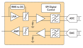
Fig 6. Data converter interface module diagram.