This article presents a comprehensive comparative evaluation of four prominent electromagnetic (EM) simulation platforms — Ansys HFSS, CST Studio Suite, COMSOL Multiphysics and ADS Momentum — applied to modeling an inset-fed rectangular microstrip patch antenna operating at 1.5 THz. A uniform antenna geometry, substrate and boundary setup are maintained to ensure consistency across all platforms. Performance metrics, including return loss |S11|, gain, directivity, radiation pattern, simulation time and computational resource usage, are analyzed in detail. The results reveal noticeable variations in solver behavior, far-field estimation and mesh handling, particularly in the terahertz range where numerical precision and stability become critical. HFSS and CST show relatively close agreement in predicted antenna characteristics, while ADS and COMSOL demonstrate distinctive strengths and constraints based on their solver architectures. As fabrication and measurement at 1.5 THz are currently not feasible in India due to limited access to nanofabrication and THz test facilities, this study focuses on a relative simulation-based comparison. The findings aim to guide researchers and engineers in selecting suitable simulation tools for terahertz antenna design based on modeling objectives, computational resources and desired analysis depth.
Microstrip patch antennas (MPAs) have become essential components in modern high frequency communication systems due to their simple structure, low profile and ease of fabrication.1,2 These antennas operate on the principle of electromagnetic radiation from a conducting patch placed above a ground plane, typically excited by a microstrip line or inset feed.3 With the advancement of wireless technologies, MPAs are increasingly being explored for higher frequency bands, particularly in the terahertz range (0.1 to 10 THz), which offers significant potential for next-generation wireless communication, imaging, sensing and medical diagnostics.4,5 Compact and highly efficient antenna designs are critical in the THz regime due to the extremely short wavelengths. MPAs are well-suited for THz frequency applications because of their planar geometry and compatibility with integrated circuit technologies.
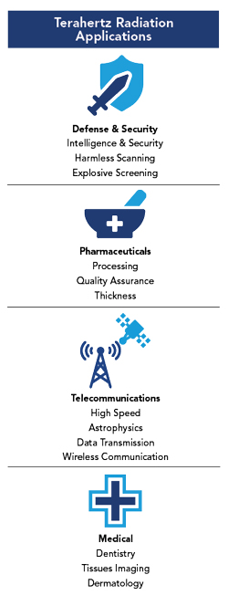
Figure 1 THz frequency applications.
THz frequencies enable ultra-high speed data transmission, non-invasive imaging and highly accurate sensing (see Figure 1). THz waves are being investigated for 6G wireless networks, offering data rates well beyond the capabilities of current microwave and mmWave systems.6 Furthermore, THz radiation is non-ionizing, making it safer for biomedical imaging and diagnostic procedures.7
Antenna design at THz frequencies presents unique challenges, including the need for precise impedance matching, high radiation efficiency and accurate modeling of material and geometrical effects. The choice of substrate materials and frequency-scaled geometries significantly influences performance in the THz domain. These challenges require the use of reliable EM simulation tools to accurately capture complex wave interactions and material behaviors at these ultra-high frequencies.
A wide range of commercial EM simulation tools, such as Ansys HFSS, CST Studio Suite, COMSOL Multiphysics and ADS Momentum, are commonly employed for antenna analysis in the THz band. These tools use different numerical methods, including the finite element method (FEM), finite integration technique (FIT) and method of moments (MoM), which vary significantly in terms of solver accuracy, speed and resource usage.8 Therefore, a direct performance comparison is essential to identify the most appropriate software for THz antenna design tasks.
Although the inset-fed rectangular patch structure is simple, its use for tool comparison at the terahertz (THz) frequency range is intentional. The primary objective of this study is to evaluate the efficiency, numerical stability and solver precision of different electromagnetic simulators for modeling behavior at ultra-high frequencies where meshing accuracy, boundary handling and convergence criteria become increasingly critical. A simple geometry minimizes geometric dependencies and ensures a fair and unbiased comparison across these platforms.
This article presents a practical comparison of four leading EM simulation platforms. Each tool is evaluated for accuracy, solver performance, far-field simulation and resource usage. The goal is to guide engineers in selecting the most suitable tool for THz antenna design.
ANTENNA AND SIMULATION METHODOLOGY
The simulations are conducted on a Microsoft Windows 11 Pro operating system using an 11th generation Intel® Core™ i7-11700F processor operating at 2.50 GHz with 32 GB of RAM.
To address the challenges of designing efficient MPAs for THz applications, this study uses a PTFE substrate with a relative permittivity (εr) of 2.1 and a thickness of 5 μm. PTFE is selected for its low dielectric constant, which supports compact antenna design, a crucial requirement at THz frequencies. Additionally, the use of a thin (5 μm) substrate height reduces radiation losses and enhances overall antenna efficiency. To ensure consistency and fairness in comparison, identical geometries, substrates, ports, boundary conditions and frequency sweeps are implemented in all four simulators.
The combination of low permittivity and minimal substrate thickness results in improved impedance matching and broader bandwidth, both critical factors in optimizing THz antenna performance. Gold is chosen as the conductive material for both the patch and the ground plane due to its stable conductivity and favorable surface resistance at high frequencies.
Figure 2 shows the top and trimetric views of the simulated structure in ADS, COMSOL, CST and HFSS, offering a comparative visualization across simulation tools. Each tool uses a distinct solver type, modeling workflow and meshing strategy. These factors influence simulation accuracy, speed and ease of use, which are critically analyzed in the following sections.
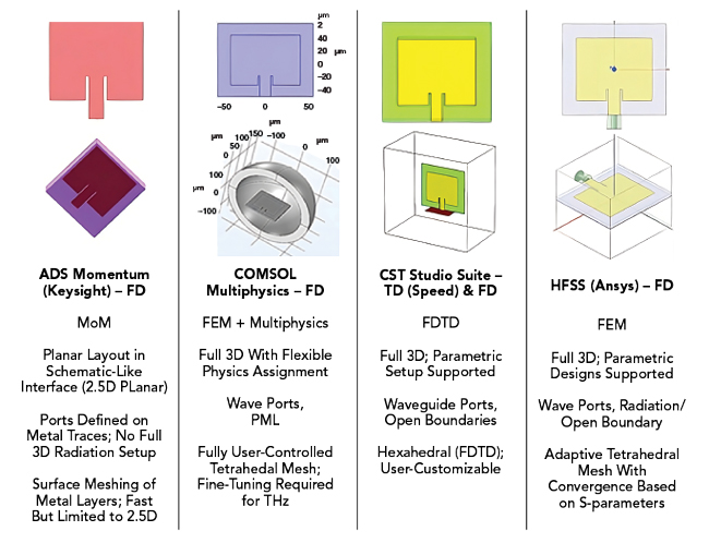
Figure 2 Top and trimetric views of the simulated structure in ADS, COMSOL, CST and HFSS simulators.
While identical geometries and materials are used across all platforms, variations in solver implementation, boundary assignment and port modeling can produce minor discrepancies, even if the model is scaled to lower frequencies. HFSS employs a 3D finite element waveport, CST uses finite integration with automatic port extensions, ADS applies a predefined 2.5D port and COMSOL employs a user-defined excitation boundary. These fundamental differences, along with solver-dependent meshing and power normalization methods, contribute to the slight variations observed in the results.
RESULTS AND COMPARISON
While most performance metrics are extracted from all four platforms, COMSOL results are limited to |S11|, gain and directivity due to computational constraints and convergence issues encountered during mesh refinement at terahertz frequencies. Key parameters compared include:
- Return loss (|S11|) and bandwidth
- Gain and directivity
- Radiation efficiency and radiated power
- Simulation speed and resource consumption.
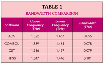
Return Loss and Bandwidth (see Figure 3 and Table 1)
- HFSS and CST show close agreement near 1.4975 THz, with return losses of -17.15 dB and -18.58 dB, respectively
- ADS predicts -31.14 dB at 1.495 THz but with limited accuracy due to its 2.5D approach
- COMSOL matches the resonance frequency but showed weaker matching (-13.78 dB) at 1.50 THz
- Bandwidths range from 55 GHz (ADS) to 101 GHz (HFSS) as listed in Table 1.
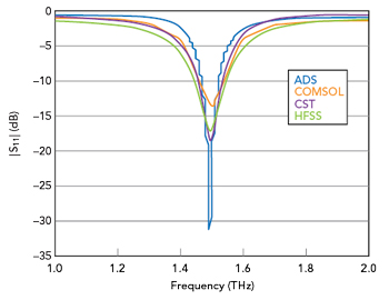
Figure 3 Simulator |S11| comparison.