

High-power microwave (HPM) weapons produce and radiate powerful electromagnetic energy, neutralizing multiple targets that fall within the beam footprint. These systems offer speed-of-light delivery, lower collateral damage, repeated engagement within performance limits and compatibility with air, ground and naval platforms. As a result, HPM are critical assets in various operations, including countering unmanned aerial systems, destroying enemy electronics and bio-effects research.
The U.S. Department of Defense (DOD) continues to advance HPM capabilities. Recent efforts include the U.S. Army’s Rapid Capabilities and Critical Technologies Office (RCCTO) collaborating with Epirus in 2023. Epirus delivered a Leonidas-driven prototype system for the U.S. Army’s Indirect Fire Protection Capability-High-Power Microwave (IFPC-HPM) program. Epirus’ Leonidas is a family of solid-state, software-defined HPM systems designed to counter swarms of electronic threats. In 2025, Epirus received a $43.5 million contract to supply second-generation IFPC-HPM systems that improve effective range, energy output and lethality.
Beyond Leonidus, the U.S. Air Force, in collaboration with the U.S. Army’s RCCTO, continues to mature the HPM counter-drone weapon known as the Tactical High-Power Operational Responder (THOR). In 2023, THOR completed a successful live demonstration against a swarm of multiple aerial targets. Longer-range air base defense capabilities are being advanced with the Counter-Electronic High-Power Microwave Extended-Range Air Base Defense (CHIMERA) system under the Directed Energy Front-line Electromagnetic Neutralization and Defeat (DEFEND) program, a joint effort between the U.S. military and industry partners such as Raytheon. CHIMERA completed live field testing in 2024, engaging static targets and tracking aerial targets throughout their flight paths.
As the DOD’s interest in HPM grows, there is significant emphasis being placed on optimizing the underlying RF signal chain. The RF portion generates the waveform, applies modulation if required, amplifies while preserving fidelity and validates key parameters that determine how effectively microwave energy engages with a target. This article outlines commercial off-the-shelf (COTS) solutions, such as signal generators, noise sources, amplifiers and power measurement instrumentation, that support and accelerate the research and development of the HPM RF signal chain.
HPM RESEARCH FOCUS AREAS
HPM weapons testing is typically performed in shielded EMI/EMC chambers to contain harmful emissions and capture controlled, repeatable measurements. As development progresses, long-range field tests are conducted at secure facilities to prevent unintentional interference.
Waveform Shaping and RF Characterization
Whether in a chamber or during fielded tests, researchers are experimenting with engineering and manipulating the actual HPM pulse.
Current work focuses on:
- Waveform design, especially across sub-9 GHz bands, using both unmodulated and modulated pulses to study different coupling mechanisms.
- Faster rise times and narrower pulse widths, which increase instantaneous peak power and can improve destructive impact at the target.
- Transmitting repetitive pulses versus a single shot, studying the effect of one transient spike compared to prolonged exposure to a burst sequence.
- Antenna architecture development, including fixed horn antennas and phased array antennas that steer the beam via phase shifting.
- RF test instrumentation, required to capture nanosecond-level transitions, narrow pulse widths and high crest factor (CF) waveforms with precision.
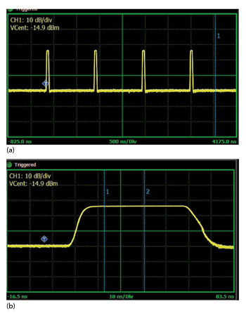
Figure 1 HPM pulse measurement (a) narrowing in on a single pulse (b) with a 5.3 ns rise time.
Figure 1a shows an example of an unmodulated HPM pulse train, requiring instrumentation capable of measuring parameters including peak and average power, pulse repetition frequency (PRF), duty cycle and nanosecond-level rise times (Figure 1b). Specifically, Figure 1 shows HPM pulse measurement, capturing 1.3 dBm peak power, -20.5 dBm average power, +952 kHz PRF, 1 μs period and 4.6 percent duty cycle of a pulse train, as well as narrowing in on a single pulse with a 5.3 ns rise time.
Weapons Architecture and Platform Integration
The RF portion is not standalone, with research uncovering how to optimize its integration into a larger weapons architecture. Before the microwave energy is transmitted, the system must clarify exactly what waveform to generate, at what precise time it should be generated and where to ultimately point the emission. This requires sensors for target identification and motion tracking, and battle management layers for key decision-making and coordination. These HPM subsystems typically work alongside other effectors, packaged into the same weapons platform. This can include other non-kinetic systems, such as high-energy lasers and electronic jammers, as well as missiles, rockets and other kinetic systems that utilize physical projectiles.
A finalized system is purpose-built for the mission it will serve. Integrating into a static installation for base defense allows for larger-scale components and longer pulse waveforms. HPM mounted onto armored vehicles or trailers not only must reduce in size but also maintain pulse fidelity during transit over rough terrain. Airborne HPM platforms are specifically designed to maintain waveform integrity, while their highly agile nature causes extreme altitude and thermal shifts. Systems operating in maritime environments require resilience against corrosive salt fog/spray and mechanical stress from various sources of vibration, such as engines and waves. Lastly, handheld or backpack systems must meet strict scale and ruggedization requirements for an individual or team to carry during an operation.
Device Development and Use Cases
Researchers are developing devices for a range of offensive, defensive and counter-defensive applications. When on the attack, HPM pulses are optimized to disable enemy electronics, whether that be a drone, aircraft, satellite or ground vehicle. For example, overloading circuits of a target that collect and transmit data can impact telemetry links, surveillance systems, GPS receivers and flight path controllers. In addition, researchers involved in bio-effects studies focus on understanding the impact an HPM pulse has on biological matter.
To protect friendly devices targeted for an assault, designers must limit vulnerabilities with robust enclosures, evaluate performance and failure points under stress and implement shielding and filtering techniques, while detection sensors can alert to any incoming high-power energy. Additional work involves designing protective wearable components that can absorb/disperse harmful energy to increase survivability. Hardened devices may be used by adversarial forces, which require counter-countermeasure research (e.g., waveform shaping, frequency agility and modulation) to develop weapons that can overcome that protection.
SINGLE-ANTENNA HPM TRANSMIT CHAIN
The transmit side of the RF chain, as shown in the single-antenna configuration in Figure 2, is used to generate the HPM pulse, apply additive white Gaussian noise (AWGN) if the application requires, amplify the waveform and capture forward and reflected power measurements before radiating through the transmit antenna.
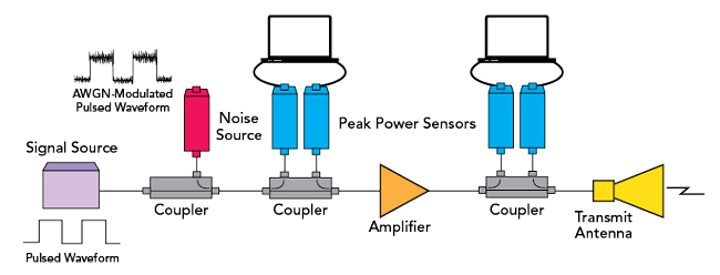
Figure 2 The transmit chain in a single-antenna HPM configuration.
Signal Generation Using Low Phase Noise RF Synthesizers
The RF test chain begins with an RF synthesizer to establish the base frequency. While different test scenarios require continuous waves (CW), many weapons use pulsed signals to achieve high peak power in short intervals to maximize damage.
High performance signal sources provide the spectral purity and low phase noise performance required to generate clean leading pulse edges. Solutions can support both CW and pulsed operation modes, featuring internal self-pulse functions as well as pulse modulation using an external stimulus signal. The ability to adjust the phase of the output is ideal for multi-channel configurations to ensure pulses arrive constructively at the target. In addition, high amplitude allows for repeatable, reliable testing, while fast frequency switching supports the development of frequency-agile systems across mission-relevant bands.
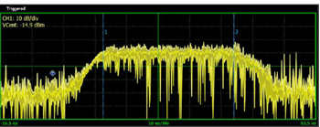
Figure 3 A noise-modulated pulse with 40 MHz AWGN and a CF of 10 dB.
Modulation with AWGN
New research shows that inserting AWGN into a short, fast-rise-time HPM pulse significantly increases effectiveness in stressing and damaging electronic circuits. AWGN adds random amplitude spikes on top of the pulse envelope, see Figure 3. The resulting noise-modulated waveform has a much higher CF or peak-to-average power ratio, defined as the ratio of a signal’s peak power to its average power. High CF waveforms contain instantaneous peaks that rise far above average power levels, which increases the pulse’s ability to push sensitive components beyond operational limits. Furthermore, dynamic AWGN waveforms can resemble the behavior of complex modulation schemes. Targeted receivers can struggle to detect and process these signals, increasing susceptibility to jamming.
Noise modules and benchtop noise sources provide precise control over noise levels and bandwidths to create the exact noise output and CF required for this emerging area of HPM research.
Driver-level Signal Amplification
The next stage in the transmit chain is signal amplification. For most HPM research and lab testing, output levels range from approximately 20 to 200 W. While these power levels are lower than operational weapons, they can generate equivalent electric-field strengths at controlled distances. Driver-level amplification, therefore, is both a safe and effective means to evaluate circuit susceptibility and analyze waveform behavior without requiring full-scale power output. These driver amplifiers can also be used in a multi-stage amplification architecture, delivering properly shaped waveforms to higher-power amplifiers later in the chain.
During testing, amplifiers must be able to accurately reproduce the characteristics of an HPM pulse. This includes supporting:
- Fast rise times (e.g., sub-10 ns) to preserve sharp leading pulse edges. If edges are distorted, the pulse delivers less impact.
- Narrow pulse widths (e.g., about 10 ns) that concentrate energy into short intervals, producing high peak power.
- High CF waveforms, which often exceed 10 dB. The amplifier must pass these instantaneous peaks without clipping or entering compression; otherwise, the waveform’s profile changes and reduces the intended effect on the device under test (DUT).
Amplified signals will be representative of the original HPM pulse with the use of high performance amplifiers. Wide frequency coverage ensures fast rise times and short pulse widths are faithfully replicated, while high linearity prevents the clipping of the highest power peaks, which is especially important for AWGN modulation.