Assessing Amplifier Performance
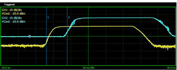
Figure 4 Amplifier pulse measurements, showing an 11 dB gain and system delay between the input (yellow) and output (blue) waveforms.
Directional couplers and peak power sensors are used to assess amplifier performance, monitoring delivered peak power, pulse shape fidelity, gain and propagation delay introduced by the system, seen in Figure 4.
With both forward and reflected measurements, engineers can determine the amplifier input return loss. The forward-coupled port samples the HPM pulse before amplification. A power sensor measures the sampled signal to verify the accuracy of the pulse shape and the power being delivered to the amplifier. A second peak power sensor connects to the reverse-coupled port to capture the power reflected back from the amplifier input. Poor return loss indicates significant reflections, which reduces the effective peak power, affects CF and interferes with the pulse’s leading edge, degrading rise time. Using a similar setup at the output, amplifier output return loss calculations uncover how well the antenna accepts the amplified HPM pulse.
SINGLE-ANTENNA HPM RECEIVE CHAIN
During testing, the transmit and receive antennas can be placed inside the EMI/EMC chamber to evaluate a high-power pulse’s effect, including radiated power and delivered field strength, on a target device. As shown in Figure 5, the receive-side measurement chain consists of the receive antenna to capture the radiated pulse, a coupler that samples a portion of the signal, a peak power sensor for power analysis and a spectrum analyzer.
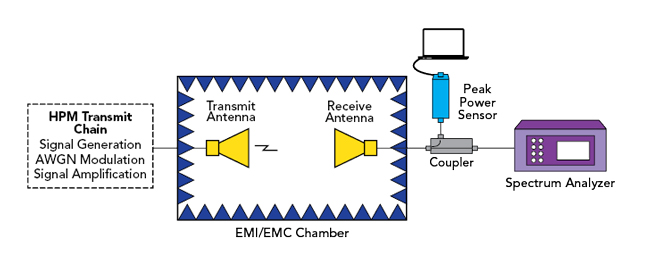
Figure 5 Receive-side setup for measuring an antenna.
Antenna Radiating Power
An antenna’s radiating power measures how much power effectively leaves and travels toward the target. Combining power measurements, known transmit/receive antenna distance, calibrated receive antenna and the chamber’s calibration factors, engineers can calculate the effective radiated power, quantifying how much energy the transmit chain delivered into space.
Received Power and Field Effectiveness
To estimate field effectiveness, it is critical to understand the actual power delivered to the target’s location. Received power measurements reveal the true stress DUTs experience after factors like propagation and free-space losses. Using the receive-side measurement chain, engineers can quantify the power at the target in dBm or dBv to determine if it is sufficient to induce the required damage.
Device Hardening
To test a device’s resilience, the DUT is placed inside the EMI/EMC chamber and exposed to pulses radiated by the transmit antenna, shown in Figure 6. The receive-side chain monitors the DUT’s response to high-power pulse exposure, enabling engineers to define the earliest points where performance deviates from what is intended. Failures range from corrupted data and brief resets to catastrophic failure, where the DUT suffers permanent damage.
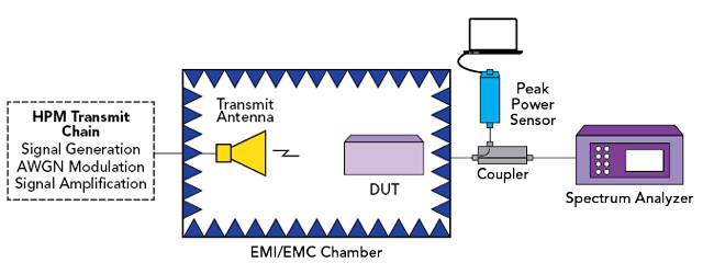
Figure 6 Test setup for evaluating a DUT’s response to an HPM attack.
MULTI-SOURCE TRANSMIT ANTENNA CONFIGURATIONS
Multi-source antenna configurations overcome antenna-level limitations on maximum radiated power. Using multiple transmit antennas allows each to operate within specified tolerances and enables a higher effective radiated power experienced at the target. These types of weapons also provide the redundancy needed in the event of an individual transmit chain failure.
In a setup with multiple antennas, such as the three separate transmit chains in Figure 7, each transmitter radiates an identical pulse toward the target. Ideally, these pulses arrive phase-aligned at the receiver, maintaining the same pulse width, spacing and timing. In this case, the pulses combine constructively to produce a single, higher energy receive pulse.
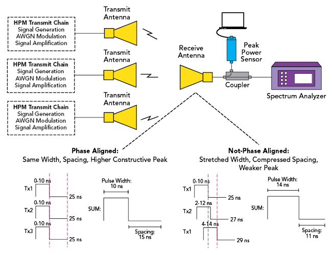
Figure 7 Multi-antenna HPM array.
Since the transmit antennas are spatially separated, each pulse will experience variations due to factors such as propagation distance and atmospheric conditions before reaching the target antenna. Antenna-induced delays and distortions further limit how tightly pulses can be phase-aligned at the target. Pulses arriving even within nanoseconds of one another can cause the composite waveform to distort and smear. The pulse width stretches, spacing compresses between pulses and the peaks no longer add constructively. Peak power, CF and the overall HPM impact are all limited as a result.
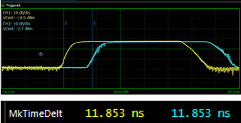
Figure 8 Measurement capturing a delay between HPM pulses of approximately 11.8 ns.
Real-time peak power sensors offering rapid rise time (e.g., < 3 ns), fast measurement speeds (e.g., 100,000 measurements per second) and fine time resolution (e.g., 100 picoseconds) can capture key pulse shape characteristics and determine the phase alignment of multi-source HPM antenna configurations, shown in Figure 8. These measurements reveal the exact arrival-time offset between transmitters, enabling engineers to apply the proper phase shift at each transmitter to ensure all pulses arrive simultaneously.
DEVICE CHARACTERIZATION
Before integrating RF components, particularly power amplifiers, into an HPM weapon, designers characterize performance under realistic, non-50 Ω conditions. Mismatches occur with high-power, wideband antennas and the operational environment causes dynamic impedance shifts from changes in frequency, power levels and platform geometry.
Using impedance tuners, load-pull measurement allows engineers to expose the DUT to a range of impedances, uncovering how performance metrics like power, gain, efficiency and linearity change as the load deviates from 50 Ω. From this data, designers are able to determine maximum deliverable power and ideal operating regions.
RF TEST INSTRUMENTATION TO ACCELERATE HPM R&D
HPM research relies on signal generation, AWGN modulation, signal amplification and waveform analysis, radiated and received power measurements and multi-source testing. Table 1 summarizes these core areas and corresponding test instruments that are driving advancements.
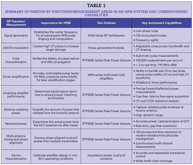
These test and measurement capabilities enable comprehensive support across the complete RF portion of HPM research and development, empowering engineers to push technological limits, strengthen mission-critical performance and ensure readiness against evolving military threats.
References
- “Epirus Delivers IFPC HPM Counter-Swarm System to U.S. Army, Developing Pathway to Field High Power Microwave Capability,” Epirus, October 2, 2023, Web: www.epirusinc.com/press-releases/epirus-delivers-ifpc-hpm-counter-swarm-system-to-u-s-army-developing-pathway-to-field-high-power-microwave-capability.
- “Epirus Receives $43 Million Contract from U.S. Army for IFPC HPM Generation II Systems,” Epirus, September 25, 2023, Web: www.epirusinc.com/press-releases/epirus-receives-43-million-contract-from-u-s-army-for-ifpc-hpm-generation-ii-systems.
- “AFRL Conducts Swarm Technology Demonstration,” Air Force Research Laboratory, October 5, 2023, Web: www.afrl.af.mil/News/Article-Display/Article/3396995/afrl-conducts-swarm-technology-demonstration/.
- “RTX’s CHIMERA High-Power Microwave System Excels During Three-Week Field Test,” RTX, January 29, 2024, Web: https://www.rtx.com/news/news-center/2024/01/29/rtxs-chimera-high-power-microwave-system-excels-during-three-week-field-test.