
CHOOSING BETWEEN COAX, TWINAX AND TRIAX CABLES
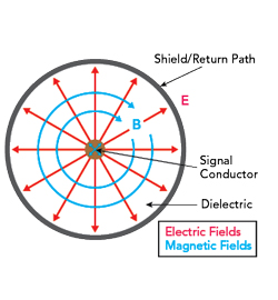
Figure 1 Coaxial cable cross-section showing the electric and magnetic fields.
RF signals move through a cable via an alternating current on the conductor. This sets up the surrounding electric and magnetic fields. The signal’s energy is sent down the line on these fields. RF energy’s behavior differs fundamentally from conventional low frequency and DC electricity because it lives primarily in these fields. Naturally, that means the RF cables that guide it must be engineered to address this distinction. Figure 1 shows a coaxial cable cross-section with the electric (E) and magnetic (B) field distribution. The red arrows illustrate the electric field extending from the center conductor to the inner face of the shield, while blue loops demonstrate how the magnetic field encircles the conductor.
There are three common cable types used for RF signal transmission, including:
- Coaxial (Coax) cable: A single center conductor surrounded by a dielectric, braided shield and outer jacket.
- Triaxial (Triax) cable: A coax core with an additional intermediate shield and insulation layer that creates a second return path to isolate sensitive signals, or bias lines, from ground noise.
- Twinaxial (Twinax) cable: Two balanced conductors twisted together inside a common shield.
COAX CABLES FOR RF SIGNAL TRANSMISSION
Coax cables are the most common configuration for RF signals. In these cables, the central conductor of the cable is a wire of either stranded or solid construction, depending on the mechanical requirements and expected frequencies. This is surrounded by an electrically conductive shield and the two are separated by an insulating layer, known as the dielectric. In short, the anatomy of coaxial cables is made of a center conductor, dielectric, outer shield and protective jacket, as shown in Figure 2.
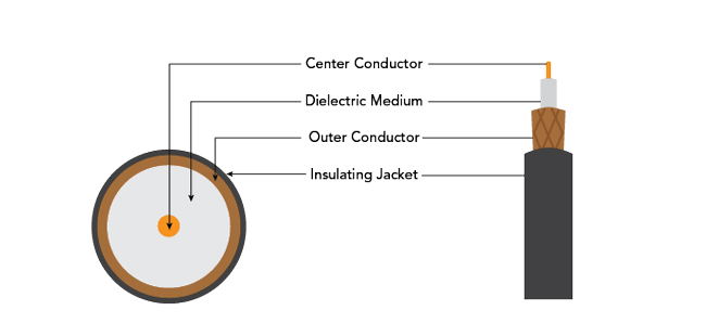
Figure 2 Anatomy of a coaxial cable.
The dielectric does not protect the center conductor from harm or adjacent cables; it shapes the cable’s electrical behavior. It is vital in controlling the relationship between the inner conductor and the shield. It ensures a precise separation of conductor and shield to control the impedance of the cable, which is also affected by the material from which the dielectric is formed.
CHALLENGES THAT COAX CABLES OVERCOME
Transmission Integrity
Coaxial cables provide a controlled impedance path so fast edges and higher frequency signals can be carried with reduced reflections and waveform distortion when properly terminated. Impedance is how much the cable resists the flow of the alternating current. The dielectric’s physical spacing and material properties determine the cable’s impedance. Coax creates the optimum physical separation between the conductor and the shield, and its permittivity governs the ease with which an electrical field can form inside it.
Some materials used in dielectric construction include:
- Solid PE – economical, rugged, ~66 percent velocity
- Foamed PE – lighter, lower εr, reduced loss
- PTFE (Teflon®) – microwave-stable, wide-temperature
- Expanded PTFE – porous, phase-stable, ultra-low loss
- FEP – extrudable fluoropolymer, low-smoke
- Air-spaced (ribbed) – mostly air, minimal attenuation.
Noise Pickup
The outer conductor in a coax cable acts as an electrostatic barrier to help reduce capacitive coupling of unwanted fields into the signal conductor, which is especially important for low-level signals routed near other wiring and equipment. How much energy is stored within the cable (capacitance) and the magnetic field caused by changes in current (inductance), both affect signal velocity. There is no perfect impedance for a coax cable; it depends on the requirements of the application.
Interference Management
Our world is awash with radiation. Some is a byproduct of the radio transmissions the modern world relies on. Other radiation can come from faulty electrical devices or even just the background radiation of the natural world. Any of these radiation sources can upset high speed links. With appropriate bonding/grounding, coaxial cables reduce the impact of radiated and magnetic field environments, and with a carefully selected grounding strategy, they can avoid ground-loop and common-mode return noise.
APPLICATIONS WHERE COAX CABLES SHINE
The controlled impedance of coax cables supports predictable transmission line behavior. This means that signal quality is maintained as frequency content increases, and proper termination minimizes reflections. The surrounding shield reduces electric field coupling from adjacent wiring and can limit susceptibility to radiated interference, especially important in dense systems where cables often share space with power wiring, motors, transmitters and other noise sources.
For example, in broadcast and cable TV systems where there are many RF carriers packed together, controlling ingress and egress is essential. Coax cables offer excellent shielding in these dense RF environments. Coax geometry is also stable and well-understood, so designers can count on consistent characteristic impedance, a predictability that helps maintain signal integrity across long lengths and through components like splitters.
Coaxial cables have been used in certain telecom trunks or baseband/broadband distribution where the signal spans a wide frequency range. Coax supports high information rates because it behaves like a controlled impedance transmission line with good shielding. That combination is useful when the signal contains fast edges or spans broad frequency content. It also has a reduced susceptibility to radiated electrical noise and a cleaner return path.
Coax keeps a stable 50 Ω or 75 Ω impedance from kilohertz IF stages up to microwave front-ends, a consistency that makes it the default single-ended choice for broadband RF.
ADDING ADDITIONAL SECURITY WITH TRIAX
There are applications where the level of protection provided by coaxial cables is not sufficient. Adding a second shield boosts immunity and cuts leakage. It also provides an independent ground reference, eliminating the multiple return paths that create ground-loop currents.
The design of a triax cable features an additional conductive layer around the core and inner shield, separated by a conventional insulating layer, as shown in Figure 3. While the more intricate construction of triaxial cable increases its cost, triax cables are important solutions for superior signal integrity.
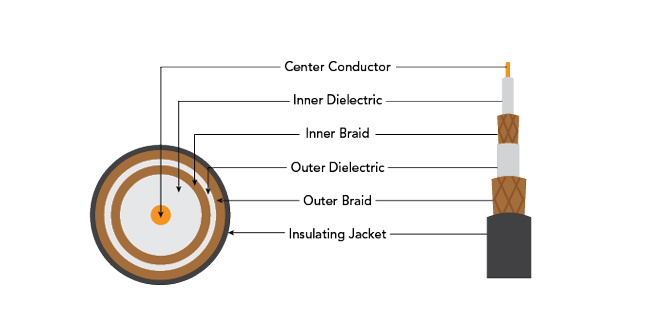
Figure 3 Anatomy of a triaxial cable.
TRIAX CABLES REDUCE LEAKAGE CURRENT EFFECTS
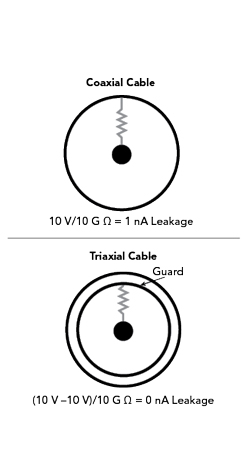
Figure 4 The guarding advantage of triax over coax.
In a coaxial cable, the signal conductor sits at some voltage while the outer shield is at ground. The plastic dielectric is never a perfect insulator (see Figure 4). Its finite resistance acts like a parasitic resistor across the measurement, and that voltage can lead to a small current flow “leakage” from the center conductor to the shield. Moisture, dirt, added length and heat can drop that resistance, and the resulting leakage can bury the true signal and delay settling.
Triax introduces a driven guard shield held at the same potential as the signal. A driven guard in a triax cable holds the inner shield at the same potential as coaxial, cancelling the voltage across the leakage path and cutting the current to zero, eliminating leakage. Any tiny residual current flows between the guard and the grounded outer shield, not through the measurement node.
TRIAX ADVANCED SHIELDING BENEFITS
Triax cables are ideal for use in driven-shield and guarded instrumentation applications because the shield is intentionally driven to reduce leakage and noise coupling. They also pair well with high frequency transducer data systems where improved noise performance helps maintain data accuracy. And because of their capability to support high information rates, and to serve as a low impedance line for pulse transmission in certain configurations, they can deliver high-current pulses as a low impedance transmission line for laser lamps or exploding bridge wire ordnance systems. Shipboard digital data-bus standards also call out triax implementations specifically.
Shielding and Ground-Loop Immunity
A driven guard shield wraps the signal core in triax cables. The guard is held at the same potential as the center conductor. With the field collapsed, leakage current vanishes and ground-loop paths never form. The outer shield still ties to chassis ground, providing a second 360-degree Faraday cage that protects against stray electromagnetic fields and static discharge that can inject microvolt errors or full-blown image artifacts into sensitive links. The result is lab-grade noise rejection for pico-amp instrumentation, HD broadcast camera feeds and low-level medical sensors.
HIGH SPEED DATA APPLICATIONS USE TWINAX CABLE
Instead of a single conductor, twinax cables use two parallel wires held in a precise relationship to each other. Surrounding the pair is a dielectric and a single, common shield. In twinax, the dielectric’s role is not to maintain the relationship between conductor and shield; it governs the impedance between the two conductors.
Twinax cable is a twisted, balanced pair surrounded by a shielding braid, as shown in Figure 5. The twist helps cancel low frequency magnetic field pickup, while the braid improves isolation from capacitive coupling and helps manage ground-loop-related interference. This can affect bandwidth, so twinax is most useful at lower frequencies as transmission losses rise with frequency.
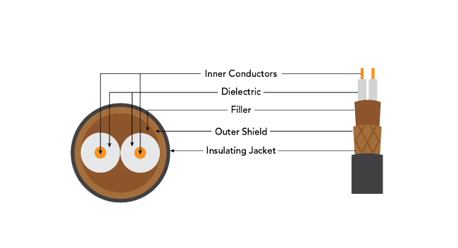
Figure 5 The internal components of a twinax cable.
Prime Twinax Use Cases
Twinaxial cables have improved low frequency magnetic-noise immunity due to the twist of the balanced pair, a defined impedance for predictable interconnect design and shielding coverage that reduces capacitive pickup, cross-talk and susceptibility to ground-loop noise. They are designed for military aircraft data-bus distribution. Twinax is used in guidance/control, navigation and communications systems. Twinax also thrives in video and broadcast distribution applications where shielded twisted-pair constructions are used at scale, as well as low frequency digital and video distribution systems where balanced signaling and shielding offer practical noise hardening. That geometry of twinax cables cancels common-mode noise, making it ideal for 10 to 100 Gb Ethernet DACs, NVLink GPU links and MIL-STD-1553 buses.
ADDITIONAL CONSIDERATIONS FOR CABLE SELECTION
Every meter of copper and dielectric adds loss. The farther users need to go without active repeaters, the lower the cable’s attenuation must be. A solid conductor coax can carry the distance load, spanning tens of meters before attenuation or dispersion forces regeneration. Triax pays for its guard with a little extra loss. Twinax trades long reach for blistering differential bandwidth, so it shines inside a rack or on a bench.
Large data centers, aircraft and telecom huts can hold thousands of links. Every added gram or dollar multiplies fast. Coax is a proven commodity technology with the lowest cost-per-meter and the widest connector ecosystem. Twinax uses less copper and dielectric than equal-performance coax, keeping short-haul cloud links lightweight and inexpensive. Triax is wider and pricier than the alternatives. Engineers reserve it for mission-critical, low-level signals where noise failures are costlier than the cable.
THE BEST CABLE FOR DIFFERENT APPLICATIONS
Coaxial, triaxial and twinaxial cables each deliver advantages in signal integrity, resistance to interference and cost. By understanding the differences between them, engineers can choose the option that provides optimal performance across applications from TV broadcasting to data centers. The composition of components is also a consideration, with increasing emphasis on flame-retardant and low-toxicity materials for public safety, as well as specialized materials for aircraft environments where exposure to fuels and cleaning solvents must be tolerated. The options for any application exist, and choosing the right cable will deliver reliable, high speed data transmission in today’s increasingly demanding environments.