

A strong need has been expressed both in the U.S. and in Europe for a high-quality feedhorn optimized for operation around 47 GHz. Previously, this frequency was a military allocation in the U.S., but now the FCC has auctioned off most of this band for commercial use. Amateur radio uses 47.1 GHz for long-distance propagation studies. The military still uses adjacent bands, so a slight modification of this design is applicable to the military as well. This new feedhorn is designed for minimal return loss with a beamwidth to produce a 10 dB edge taper for a reflector antenna with an f/d ratio of 0.6 and a 90-degree subtended angle by the feed. It has nearly no side or back lobes. To accomplish this at a wavelength of 6.38 mm, tight machining tolerances are needed. The antenna is divided into several pieces to make it easier to fabricate accurately and to produce in large quantities.
This feedhorn is a novel augmentation of the dual-mode feedhorn patented by Philip D. Potter at Jet Propulsion Laboratory in 1962.1 It is important to note that this design includes the removal of the phasing chamber in Potter’s design. This was described by Herbert M. Pickett and John C. Hardy in 1984.2,3 The second augmentation is this author’s addition of a simple, easy-to-fabricate and almost lossless internal transition from the native internal circular waveguide to a WR22 rectangular waveguide input. This article presents a design of a third change to the Pickett-Potter horn as well.
The Pickett-Potter horn has a circular waveguide input that contains the TE11 mode of the desired signal (see Figure 1). The input is diameter d1, and there is an abrupt step to a larger diameter d2 at the beginning of the flared horn. The dimension d2 is such that some TM11 mode is generated in this region. The TM11 higher-order mode generated at the step up to d2 is at a level of approximately 15 percent of the dominant mode. Potter found through experimentation that the primary mode should contain approximately 85 percent of the total energy, and the higher-order mode the remaining 15 percent. Other higher-order modes are either cut off or are not excited due to symmetry.
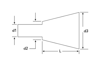
Figure 1 Pickett-Potter horn block diagram.
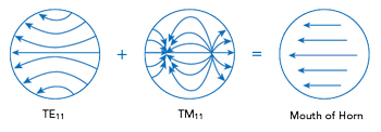
Figure 2 Combination of modes at the conical flare opening.
In the Pickett-Potter horn, the length of the flare L and the final open end diameter d3 are chosen so that the dominant mode and the TM11 mode arrive at the mouth of the flare d3 with the phase values shown in Figure 2. Since the two modes have different guide wavelengths, the flare length is optimized to achieve this. Once the correct phases for the two modes are achieved, the higher-order mode cancels the dominant mode near the conducting wall of the open end of the conical flare. This results in a significant reduction of side and back lobes. An almost complete cancellation is possible.
This article presents a third change to the Pickett-Potter horn. Instead of using the abrupt step between the circular waveguide d1 and the diameter of the flared taper input d2 to generate the TM11 mode, this horn uses the small diameter circular waveguide solely as a complex impedance match between an oval transition and the input to the tapered horn. In this design, the TM11 higher-order mode is generated within the flared taper and the open mouth d3 at the end of the taper. This requires extensive optimization.
Many offset-fed satellite dish antennas are available with an f/d of 0.6. Most offset dishes have an f/d of 0.6 or 0.8. Also, driving the Cassegrain secondary subreflector of a circular parabolic dish usually requires an f/d of 0.6 to 0.8. The difference in the edge taper with an f/d ratio of 0.6 or an f/d ratio of 0.8 is within 2 dB at ± 45 degrees, so this feedhorn can be used with either. This article concentrates on an f/d = 0.6 design and results, which corresponds to a -10.5 dB full beamwidth of 90 degrees.
RECTANGULAR TO CIRCULAR WAVEGUIDE TRANSITION BACKGROUND
The original idea upon which this transition is based was J. R. Pyle’s work in Southern Australia in 1964.4 All the other transitions reviewed, including Dan Bathker’s,5 require manufacture by electroforming or very complex non-planar machining with soldering or welding. One interesting paper is by Stuchly and A. Kraszewski.6 Another similar design is by Eric Holzman, who roughly adopted this in his manufacture of a V-Band antenna.7 However, he depended on making the rectangular waveguide completely oval, and it was not an easily manufacturable design.
47 GHz Dual-Mode Feedhorn Design
The matched transition from the WR22 rectangular waveguide TE10 mode to the circular waveguide TE11 mode is initially done as a homogenous structure. The impedance, cutoff frequency fc and guide wavelength lg of the WR22 waveguide are calculated. Then the inside diameter of a circular waveguide is selected to provide an identical impedance, cutoff frequency and guide wavelength. The calculated diameter of the circular waveguide is .263 in. corresponding to a value of ka = 3.295, where k is the wave number, and a is the radius of the circular waveguide. At this frequency, the TE11 and TM01 modes are above cutoff with kca values of 1.841 and 2.405, respectively, with kc being the cutoff wave number. The TM01 mode is not excited by the rectangular waveguide TE10 mode because of symmetry. For use at 47.1 GHz, it is unnecessary to use a multi-stepped transition because the bandwidth of one matching section is more than enough for the application.
Now the first serious manufacturing problem is apparent. The quarter-wave matching section designed at this frequency is too thin to manufacture, so an odd multiple of ¼ λg is chosen (i.e., 5/4 λg), where λg is the full guide wavelength. However, the thickness is not an exact multiple of ¼ λg because the guide wavelength within the oval matching section changes due to its shape. This requires recalculation and optimization.
The wavelengths of the primary circular TE11 mode and the higher TM11 mode are clearly not identical either. Given that the two modes have different wavelengths and different power levels, optimization techniques work far better than electromagnetic calculations.
The cylindrical waveguide diameter is slightly changed from .263 to .2711 in. This provides a better match to the rectangular waveguide. The final dimensions (in inches) of the four parts of the feedhorn are shown in Figure 3.
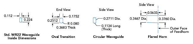
Figure 3 Final dimensions of the feedhorn’s four sections (in.).
The flared horn with its abrupt step presents a complex impedance to the circular waveguide. Therefore, optimization of several parameters is done iteratively in groups to achieve the desired result of low side and back lobes simultaneously, with a very good match to the WR22 waveguide. Reoptimizing with changes of the inner and outer diameters of the flared horn is done many times to achieve the correct beamwidth while continuing to suppress the side and back lobes.
Physical Structure
The physical structure comprises a mounting plate for the WR22 rectangular waveguide flange, followed by an oval matching section to a circular waveguide that drives a tapered horn with a low flare angle (see Figure 4). The assembled feedhorn is shown in Figure 5.
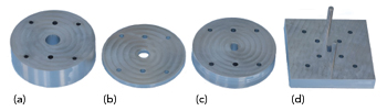
Figure 4 Photograph of the prototype’s four sections: flared horn (a), circular waveguide (b), oval transition (c) and waveguide mounting plate (d).

Figure 5 Assembled prototype.
There is a manufacturing reason why the UG-599/UM square waveguide flange is chosen rather than the more common UG-383/U round flange. Round mmWave flanges must include two precision locating pins and four threaded screw holes. More problematic, the UG383/U flange is larger than the square flange and therefore necessitates a larger diameter feedhorn.
There are many adapters available between the round and rectangular flanges in the WR22 waveguide for the users of this feedhorn. One can also use a WR22 waveguide that has the UG-599/UM rectangular flange already attached.