
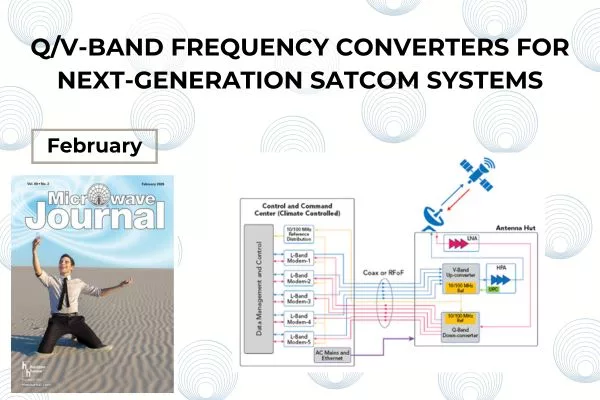
INTRODUCTION
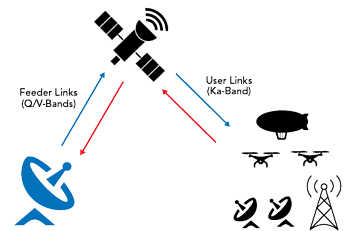
Figure 1 Typical application scenario.
Next-generation satellite communication (satcom) systems targeting data rates in excess of Tb/s, such as ViaSat 3, are expected to replace traditional, aging broadband systems. High-throughput satellite (HTS) and very high-throughput satellite (VHTS) systems operating at multiple Ka-, Q- and V-Bands are gaining popularity in practical realisation of such data rates, which were perceived as almost impossible to achieve in commercial applications not long ago.1-3 These new generation satellite systems are deemed vital to a diverse range of applications from mega-constellation LEOs, future MEOs and high-altitude platforms to unmanned aerial vehicles, drones and cellular backhaul.
The effective use of the Q- and V-Bands has the potential to double the total satellite bandwidth available. The Q/V spectrum is currently sparsely populated, and physically smaller antenna sizes offer many advantages, including reduced mass in satellite hardware. Narrower beam widths allow reduced satellite spacing and a denser constellation. Q/V-Band feeder links reduce the number of gateways required to support system capacity and free up spectrum allocated to Ka-Band gateways, which can be used for user links, as illustrated in Figure 1.
The main drawbacks of the Q/V satellite system are the increased propagation and atmospheric losses compared to Ka-Band counterparts and less mature technology in the choice of high frequency components such as amplifiers, mixers, filters and passive components, which inevitably increase the cost of these converters. These are the main reasons that Q/V-Band implementation of satcom is currently limited to gateways and satellites rather than to direct users.
In a typical uplink to satellite scenario, the V-Band frequency converter is utilized after the modem and before the high power amplifier (HPA), as illustrated in Figure 2. The output power of the V-Band frequency converter itself would be too low to overcome the signal path loss, which is mostly composed of propagation loss, atmospheric loss, depolarization due to Faraday rotation and ionospheric scintillation. Although pencil-beam high gain antennas are employed at the ground station terminals, there is still a need for an HPA to establish seamless communication between the ground station and the satellite. Furthermore, most modems have data ports through fibre or Ethernet, which makes them more suited for indoor units where they can be managed effectively. HPAs, on the other hand, need to be close to the antenna or to the antenna control room to minimize losses and electromagnetic shielding. As signal loss increases with frequency, it becomes necessary to co-locate the frequency converter and HPA as close to one another as practical, and likewise HPA to the antenna feed as possible.
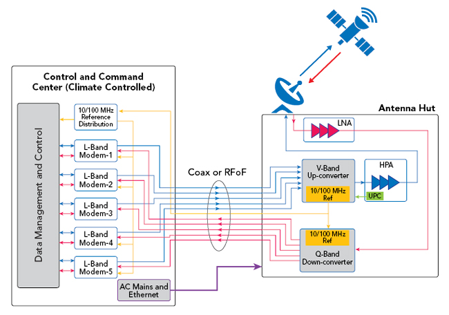
Figure 2 Satellite link configuration for Q/V-Band satcom.
The RF characteristics of HPAs are also different than modems as their linearity, group delay and efficiency depend on the levels of input and output signal and their physical operational environment. Thus, an up-converter not only translates the L-Band modem frequency to V-Band but also serves as an intermediary to maintain the linearity requirements of both modem and HPA while providing adequate gain to overcome the loss between the two ends of the communication link.
The downlink scenario of the communication link resembles that of the up-converter for most traditional and legacy satcom systems. However, with the usage of spot-beams, satellite frequency reuse and polarization diversity of traditional bent-pipe architectures have been replaced with more complicated systems, where software-defined radio architectures gained increased popularity with adaptive and reconfigurable frequency translation and signal routing. Thus, the downlink signal bandwidth, data rate and signal modulation can dynamically change, which must be accounted for at the down-converter. Unlike HPAs, the low noise amplifiers (LNAs) are more standard, and the noise figure, linearity and signal distortion requirements are well known to affect the system performance within a predefined signal bandwidth. However, traditional LNAs aim to minimize noise figure and maximize gain over a narrow bandwidth, tuned to be reconsidered for wideband systems, where gain variation should be corrected before the HPA. The distortion added to the received satellite signal should be minimal at the frequency conversion stage, namely at the down-converter. Thus, the linearity requirement of the Q-Band down-converter is expected to be considerably better than that of a typical Ku-Band down-converter.
To describe multiple modems connected to a V-Band up-converter, the term multi-channel is often used in product specifications. In strict terms, a communication channel refers to a physical transmission medium such as wire, fibre or radio in the context of telecommunications. However, in broadcasting terminology, a channel is usually referred to as a data stream within the transmission or reception bandwidth. Thus, a bandwidth can be divided into sub-bands, where each sub-band is called a channel. This can be regarded as the classical definition of channel, which is somewhat different than its modern usage, where multiple access systems, such as code-division or time-division, utilize the entire bandwidth for all user channels to increase the capacity and data rate. L-Band modems shown in Figure 2 are combined to form a wideband signal that has been translated to V-Band and transmitted to the satellite (see Figure 3). In classical frequency division systems, the channels are separated by guard bands to minimize inter-channel interference and leakage. Adjacent channel power ratio (ACPR) is usually a very strict parameter that directly impacts the system performance. In the satellite broadcasting industry, the distribution of channels within a given satellite bandwidth is usually controlled by the satellite operators and system engineers. Unlike a typical wireless link, where there is no or minimal control over the source frequency and information, satellite operators can define modem output frequencies for minimal interference. Satellite system operators are usually experts in link configuration and would rather control the frequency distribution of combined signals than reduce the expensive bandwidth for fixed channel separation. In a typical wireless system, usually 10 percent of the bandwidth from each end, which amounts to 20 percent of the allocated bandwidth, would be reserved for guard bandwidth, which translates to almost 200 MHz of unused bandwidth in satcom. With high peak-to-average ratio modulated signals, this guard band would be widened even further to maintain the same ACPR value. This allocation of bandwidth is deemed to be an underutilized resource in satellite broadcasting and communication. Therefore, edge-to-edge stacking up of L-Bands without leaving any guard band is possible with appropriate reservations in communication planning.

Figure 3 L-Band translation of input bands to V-Band.
General specifications for frequency converters are outlined next. Critical converter features that impact Q/V-Band frequency converters, such as isolation, phase noise and group delay, are also detailed in subsequent sections.
GENERAL SYSTEM SPECIFICATIONS
Single or multi-channel L-Band signals can be translated to V-Band using either a single or dual conversion. Using legacy L-Band modems, a general dual-stage architecture can provide enough flexibility in system design and component selection. With the emergence of C-Band modems, a single channel with an excess of 2 GHz instantaneous bandwidth can also be considered. However, the limited availability of such modems precludes their widespread use in commercial markets at present.
The down-converter architecture is similar to that of the up-converter, but the RF specifications can be different. In the up-converter, the linearity of the wideband signal that is formed from L-Band signals is mostly dictated by the last stage V-Band section, whereas in the down-converter, this requirement is mostly transferred to the final L-Band output stage. The presence of an LNA at the front-end eases noise figure requirements of the down-converter and places greater emphasis on the linearity of subsequent sections.
General system specifications for up- and down-converters are summarized in Table 1.

CHANNEL-TO-CHANNEL ISOLATION
Apart from in-band and out-of-band spurs, adjacent channel leakage at the input or output is also undesirable and must be kept as low as possible. A possible leakage scenario is illustrated in Figures 4 and 5, where Channel 2 is coupling to other channels. The coupled signal would appear at the input modem band of other channels for input-to-input coupling in Figure 4, where the conducted coupling must go through the combiner and reverse direction of the victim converter channel, which is usually much better than its forward gain. Thus, input-to-input coupling can be as low as -60 dBc. The out-to-out coupling is solely determined by the converter selectivity and combiner/splitter isolation between the channels. Since L-Band channels are stacked back-to-back, band edges shared by adjacent channels can only be isolated by the combiner isolation theoretically.
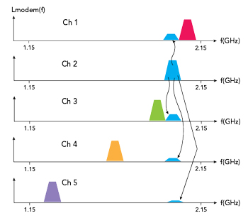
Figure 4 Channel 2 leakage to other channels (input-input coupling).
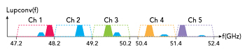
Figure 5 Channel 2 leakage in output spectrum.