PHASE NOISE
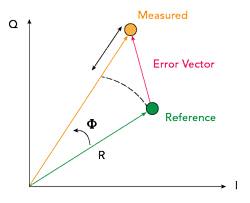
Figure 6 Illustration of EVM.2
Phase noise is one of the most critical metrics that impacts system performance. In a typical digital constellation, the relation between PN and error vector magnitude (EVM), as seen in Figure 6, can be established. EVM can be expressed by Equation 1: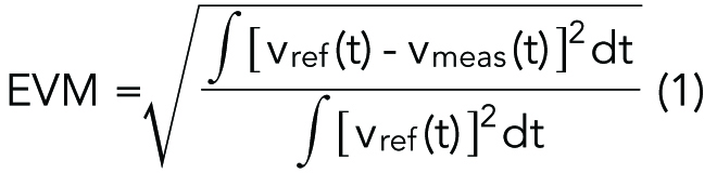
where vref (t) and vmeas (t) are expected and measured signals, respectively. For |φ(t)|<<1, the expression can be approximated by Equation 2:

and EVM can be readily stated as seen in Equation 3:

Therefore, the maximum EVM for a chosen digital modulation also sets the upper bound for maximum phase noise. Although this integrated phase noise is a critical factor, spurs in the phase noise spectrum can also lead to increased EVM and translation of unwanted signals into the band.
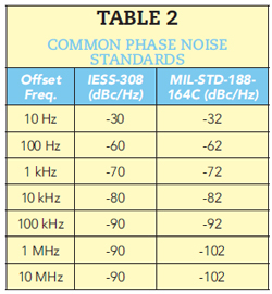
The IESS-308 Standard is often an adequate performance metric for Ku-Band systems.4 The U.S. military, however, has been using slightly tighter phase noise specifications as outlined in MIL-STD-188-164C.5-6 Both specifications are summarized in Table 2.
In the up-converter module, a 36 GHz signal source is used to translate the intermediate band (IF) to V-Band. The phase noise of this signal would be the dominant contributor to the up-converter phase noise. The signal is first generated using a synthesized source of 18 GHz, and with the help of a doubler, 36 GHz is obtained. The phase noise at 18 GHz is shown in Figure 7.
The phase noise for the entire five-channel V-Band block up-converter is also measured, and its performance at the upper band edge, namely 52.4 GHz, is displayed in Figure 8. Even at this extreme band edge, the unit easily satisfies IESS standards and performs very close to MIL standards.
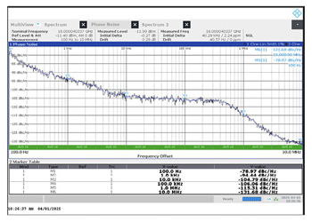
Figure 7 Measured phase noise at 18 GHz.
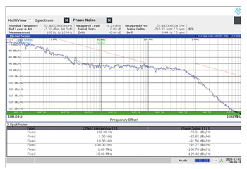
Figure 8 Measured phase noise at 52.4 GHz.
GROUP DELAY
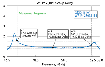
Figure 9 Measured group delay of waveguide filter at V-Band.
Group delay variation is also a critical metric in system design and link calibration. A waveguide filter at the final output of the V-Band up-converter and input of the Q-Band down-converter is needed to provide good rejection for out-of-band signals and spurs. This filter is built and measured, and its measured group delay response is shown in Figure 9. Measured data are processed in AWR Microwave Office with other building blocks.
CONCLUSION
Critical design aspects of wideband Q/V-Band frequency converters are discussed. Apart from legacy converter designs, the target 5 GHz conversion bandwidth has key design challenges in terms of in-band (channel-to-channel) leakage and spurs, low phase noise to accommodate higher modulation and coding and low group delay variation. To overcome these critical issues, the design is made flexible and scalable in terms of submodules that separate the final translation band from the L-Band and intermediate bands. That way, wider single-channel modems such as 2 GHz C-Band modems can also be utilized with the modification of submodules. The use of IF combiners/splitters permits such scalability.
Uplink power control (UPC) settable up-converters would be an essential part of these systems, as fade margins would be higher compared to Ka-Band counterparts. UPC based solely on beacon feedback in an open loop system is usually inferior to systems that employ an additional closed loop system based on a test-loop-translator of the pilot channel. In traditional systems, UPC is used to adjust HPA with a limited linearity range. When UPC is simultaneously utilized in the up-converter and HPA, the dynamic range or the linearity range of the satellite link can be enhanced.
Another important feature of these new generation converters is their ability to synchronize all other subcomponents in the satellite link to a common reference for minimum frequency translation error. With the emergence of software modems and digital IF products, not only frequency reference but also time reference through 1 pps GPS would become essential. Hence, these converters are expected to lock or derive their internal reference from GPS disciplined references and synchronize all internal sources to this common time reference to maintain commercial-grade target Tb/s high throughput rates.
ACKNOWLEDGEMENT
This work is partly funded by the European Space Agency under Contract No. 4000128210/19/NL/MM/ra.
References
- H. Fenech, S. Amos, A. Tomatis and V. Soumpholphakdy, “High Throughput Satellite Systems: An Analytical Approach,” IEEE Transactions on Aerospace and Electronic Systems, Vol. 51, No. 1, January 2015, pp. 192–202, doi: 10.1109/TAES.2014.130450.
- K. Yegin, B.L. Brown and P.G. Gouws, “Phase Noise Modelling for Ka-Band VHTS Systems,” ARMMS Conference, September 2023, pp. 1–6.
- M. M. Bilgic and K. Yegin, “Low Profile Wideband Antenna Array With Hybrid Microstrip and Waveguide Feed Network for Ku Band Satellite Reception Systems,” IEEE Transactions on Antennas and Propagation, Vol. 62, No. 4, April 2014, pp. 2258-2263, doi: 10.1109/TAP.2013.2297696.
- “Digital Video Broadcasting (DVB); Second Generation Framing Structure, Channel Coding and Modulation Systems for Broadcasting, Interactive Services, News Gathering and other Broadband Satellite Applications; Part 1: DVB-S2, DVB-S2,” ETSI EN 302 307-1 V1.4.1 (2014-11).
- “Interoperability of Superhigh Frequency (SHF) Satellite Communications Phase-Shift Keying (PSK) Modems,” MIL-STD-188-165B, March 26, 2018.
- L. Gonzalez, J. Rippon and J. Besse, “Phase Noise, SATCOM and MIL-STD-188-165B,” IEEE Military Communications Conference (MILCOM), 2019, pp.13–16.