
The validation requires disconnecting the cables from the oscilloscope’s channels 3 and 4 and connecting each to a Keysight N9010A spectrum analyzer. The results are shown in Table 1. Pout of the main channel shows minimal difference between measurement approaches, indicating that the power calculations based on the measured voltage waveforms are accurate. However, power levels in the adjacent channels differ by up to 1.7 dB, impacting ACPR (see Table 1). These discrepancies are attributed to the oscilloscope’s reduced dynamic range compared to the spectrum analyzer. According to the oscilloscope’s data sheet,27 the vertical resolution is 8 bits with averaging off and 12 bits with averaging on (used only for phase calculations), resulting in a theoretical dynamic range of approximately 48 dB and 72 dB, respectively. In practice, the oscilloscope’s dynamic range is also influenced by the vertical scale selected for the measurement; a lower V/div setting reduces the maximum voltage that can be measured without clipping.
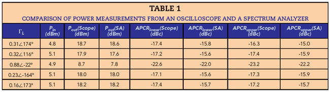
Also, the directional couplers that separate the incident and reflected waves have a coupling factor of approximately 35 dB, consequently attenuating the measured waves by 35 dB. This makes it more challenging to accurately measure lower power levels, such as those in the adjacent channels. This technique could benefit from using directional couplers with a lower coupling factor to overcome the disadvantage of an oscilloscope’s reduced dynamic range compared with equipment like a spectrum analyzer. Another option to improve dynamic range is to implement a statistical averaging technique.28
CONCLUSION
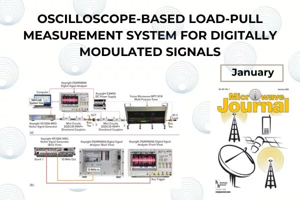
Load-pull measurements are performed with modulated signals using an oscilloscope, removing the need for complex equipment like an LSNA, NVNA or VNA. The proposed approach streamlines the calibration process by eliminating the need for prior tuner characterization, waveform corrections and a comb generator for phase reference. It provides accurate load-pull contours for output power, gain, drain efficiency, PAE and ACPR. Additionally, this work includes all the necessary details for setting up the measurement system and assembling the test bench. Experimental validation with an ATF38143 GaAs FET demonstrates the effectiveness of this method in optimizing the efficiency-linearity tradeoff in power amplifier design.
References
- L. Angrisani, “Experimental Assessment of Modulated S-parameters Reliability in Modeling and Testing Wideband Radio Frequency Amplifiers,” IEEE Transactions on Instrumentation and Measurement, Vol. 55, No. 5, October 2006, pp. 1474–1479.
- S. A. K. Kahil, S. Laurent, R. Quéré, J. Sombrin, D. Floriot, V. Brunel and C. Teyssandier, “Linearity Characterization of GaN HEMT Technologies Through Innovative on-Wafer Multi-Tone Load-Pull Measurements,” 11th European Microwave Integrated Circuits Conference, October 2016.
- J. Martin, M. Moldovan, C. Baylis, R. J. Marks, L. Cohen and J. de Graaf, “Radar Chirp Waveform Selection and Circuit Optimization Using ACPR Load-Pull Measurements,” IEEE Wireless and Microwave Technology Conference, April 2012.
- X. Konstantinou, J. D. Albrecht and J. Papapolymerou, “Using Active Load-Pull with Modulated Signals to Optimize Power and Linearity,” 94th ARFTG Microwave Measurement Symposium, January 2020.
- M. Marchetti, G. Avolio, M. Squillante, A. K. Doggalli and B. Anteverta-Mw, “Wideband Load Pull Measurement Techniques: Architecture, Accuracy and Applications,” 92nd ARFTG Microwave Measurement Conference, January 2019.
- S. Alsahali, D. Gecan, A. Alt, G. Wang, S. M. H. Syed Anera, P. Chen, S. Woodington, A. Sheikh, P. Tasker and J. Lees, “A Novel Modulated Rapid Load Pull System with Digital Pre-Distortion Capabilities,” 93rd ARFTG Microwave Measurement Conference, June 2019.
- P. Ghanipour, S. Stapleton and J. -H. Kim, “Load–Pull Characterization Using Different Digitally Modulated Stimuli,” IEEE Microwave and Wireless Components Letters, Vol. 17, No. 5, May 2007, pp. 400–402.
- J. Verspecht, A. Stav, T. Nielsen and S. Kusano, “The Vector Component Analyzer: A New Way to Characterize Distortions of Modulated Signals in High-Frequency Active Devices,” IEEE Microwave Magazine, Vol. 23, No. 12, December 2022, pp. 86–96.
- J. Benedikt, R. Gaddi, P. Tasker, M. Goss and M. Zadeh, “High Power Time Domain Measurement System with Active Harmonic Load-Pull for High Efficiency Base Station Amplifier Design,” IEEE MTTS International Microwave Symposium Digest, Vol. 3, June 2000, pp. 1459–1462.
- V. Teppati, S. Pinarello, A. Ferrero and J. -E. Mueller, “An Unconventional VNA-based Time-Domain Waveform Load-Pull Test Bench,” Asia-Pacific Microwave Conference, December 2010.
- V. Teppati, A. Ferrero, M. Garelli and S. Bonino, “A Comprehensive Mixed-Mode Time-Domain Load- and Source-Pull Measurement System,” IEEE Transactions on Instrumentation and Measurement, Vol. 59, No. 3, March 2010, pp. 616–622.
- F. De Groote, J. -P. Teyssier, J. Verspecht and J. Faraj, “High Power on-Wafer Capabilities of a Time Domain Load-Pull Setup,” 71st ARFTG Microwave Measurement Conference, June 2008.
- F. De Groote, P. Roblin, Y. -S. Ko, C. -K. Yang, S. J. Doo, M. V. Bossche and J. -P. Teyssier, “Pulsed Multi-Tone Measurements for Time Domain Load Pull Characterizations of Power Transistors,” 73rd ARFTG Microwave Measurement Conference, June 2009.
- F. De Groote, O. Jardel, J. -P. Teyssier, T. Gasseling, J. Verspecht, V. Mallette and C. Tsironis, “On-Wafer Time Domain Load-Pull Optimization of Transistor Load Cycle with the New Multi-Harmonic MPT Tuner,” 69th ARFTG Conference, June 2007.
- I. Volokhine, “An Extension of Existing Real-Time Load Pull Systems to Perform Voltage/Current Waveform Reconstruction,” 71st ARFTG Microwave Measurement Conference, June 2008.
- M. Molina-Ceseña, J. A. Reynoso-Hernández, M. A. Pulido-Gaytán, J. R. Loo-Yau and M. C. Maya-Sánchez, “Experimental Investigation of Resistive-Reactive Class-J Mode Using Time-Domain Low-Frequency Active Harmonic Load-Pull Measurements,” IEEE Microwave and Wireless Components Letters, Vol. 32, No. 1, January 2022, pp. 96–99.
- D. F. Williams, K. A. Remley, J. M. Gering, G. S. Lyons, C. Lineberry and G. S. Aivazian, “Comparison of Large-Signal-Network-Analyzer Calibrations,” IEEE Microwave and Wireless Components Letters, Vol. 20, No. 2, February 2010, pp. 118–120.
- S. Gustafsson, M. Thorsell, J. Stenarson and C. Fager, “An Oscilloscope Correction Method for Vector-Corrected RF Measurements,” IEEE Transactions on Instrumentation and Measurement, Vol. 64, No. 9, September 2015, pp. 2541–2547.
- J. Scott, P. Blockley and A. Parker, “A New Instrument Architecture for Millimetre-Wave Time-Domain Signal Analysis,” ARFTG 63rd Conference, June 2004.
- M. Lindquist, P. Roblin and N. C. Miller, “New Real-Time Pulsed-RF NVNA Testbed for Isothermal Characterization of Traps in GaN HEMTS,” IEEE/MTT-S International Microwave Symposium, June 2023.
- M. Lindquist and P. Roblin, “Calibration of an Oscilloscope-Based NVNA for Periodic Modulated Signals,” 103rd ARFTG Microwave Measurement Conference, June 2024.
- A. Ferrero and U. Pisani, “An Improved Calibration Technique for on Wafer Large-Signal Transistor Characterization,” IEEE Transactions on Instrumentation and Measurement, Vol. 42, No. 2, April 1993, pp. 360–364.
- A. Villagran-Gutierrez, J. R. Loo-Yau, E. A. Hernández-Domínguez, B. E. Figueroa-Reséndiz, P. Moreno and J. A. Reynoso-Hernández, “A Time-Domain Vector Network Analyzer Suitable to Characterize Passive and Active Devices,” IEEE MTT-S Latin America Microwave Conference, December 2023.
- J. Webster and H. Eren, “Measurement, Instrumentation, and Sensors Handbook: Electromagnetic, Optical, Radiation, Chemical, and Biomedical Measurement,” CRC Press, 2017.
- G. Gonzalez, “Microwave Transistor Amplifiers: Analysis and Design,” Prentice Hall, 1997.
- G. Engen and C. Hoer, “Thru-Reflect-Line: An Improved Technique for Calibrating the Dual Six-Port Automatic Network Analyzer,” IEEE Transactions on Microwave Theory and Techniques, Vol. 27, No. 12, December 1979, pp. 987–993.
- Infinium 90000 Series Oscilloscopes, Data Sheet, Keysight Technologies, Web: https://www.keysight.com/us/en/assets/7018-01734/data-sheets-archived/5989-7819.pdf.
- C. Fager and K. Andersson, “Improvement of Oscilloscope Based RF Measurements by Statistical Averaging Techniques,” IEEE MTT-S International Microwave Symposium, June 2006.