
In the world of military and aerospace electronics, compliance testing is not just a box to check; it is a matter of mission success and safety. Among the many procedures outlined in MIL-STD-461, one stands out for its rigor: RS103, the radiated susceptibility test. For systems that must withstand 200 V/m field strength, RS103 represents a formidable challenge. Within this procedure, the frequency range of 30 to 200 MHz has long been a thorn in the side of engineers and test labs.
THE PAIN POINT OF BICONICAL ANTENNAS IN HIGH-FIELD TESTING
Traditionally, the solution has been the biconical antenna, a legacy design that has served the industry for decades. Yet when pushed into high-field territory, its shortcomings become clear. Engineers face high voltage standing wave ratios (VSWR), unpredictable radiation patterns and excessive harmonic emissions. In fact, it is not unusual for harmonics to exceed the fundamental signal, undermining the integrity of the test.
Dimensional constraints add to the frustration. MIL-STD specifies that the receive biconical antenna should measure 137 centimeters overall. While this requirement does not apply to radiated susceptibility, many labs prefer to use a single antenna for both emissions and susceptibility testing. That means the balun must remain small enough to fit emissions requirements, limiting its ability to handle the power needed for RS103. The result is an antenna that cannot reliably generate 200 V/m at one meter or greater distances without being oversized and prohibitively expensive.
The inefficiency of the biconical antenna also creates standing waves in the test chamber, a dangerous condition for sensitive amplifiers and other test equipment. For facilities tasked with high-field testing, these limitations translate into risk, cost and wasted time.
SOLVING THE BICONICAL ANTENNA PROBLEM
The industry has reached a point where a new approach is not just desirable, it is essential. To achieve the required field strength without jeopardizing amplifiers or test components, engineers need an antenna that can adapt dynamically to frequency changes, reduce standing waves, suppress harmonics and maintain a low VSWR. In short, the solution must be smarter, more efficient and more reliable than the traditional biconical antenna.
DIRECTED DIPOLE / YAGI ANTENNA APPROACH
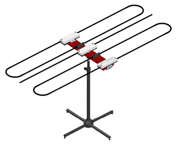
Figure 1 Model 3170 Intell-I-Tune™ Antenna System.
Enter the Yagi-style antenna with tunable dipole elements, a design that reimagines low frequency testing as shown in Figure 1. Unlike fixed-length antennas, which are inherently narrowband and power hungry, a tunable dipole system can adjust itself to the environment. Stepper motors, guided by precise algorithms, alter dipole lengths for each frequency and polarization. This ensures true resonance across the band and keeps VSWR below 3:1—often closer to 1.5:1—providing a clean, efficient signal path.
Harmonic emissions can be reduced by more than 25 dB, delivering a cleaner signal and eliminating the need to overdrive amplifiers. Because the antenna operates at the fundamental frequency, smaller and less costly amplifiers can be used without sacrificing compliance. This reduces system complexity and lowers overall cost.
Automation adds another layer of value. Once tuning files are stored, the antenna automatically adjusts to the correct configuration, eliminating manual intervention. This hands-free operation increases throughput, minimizes human error and ensures repeatable results. For busy test labs, the ability to streamline operations while maintaining accuracy is key.
OPTIMIZED ANTENNA TEST SOLUTION
Low frequency testing has always demanded a different approach than microwave or high frequency ranges. A tunable, automated antenna system addresses these unique needs by offering multiple configurations, maintaining low VSWR and delivering consistent performance. The result is higher throughput, improved efficiency and greater confidence in test outcomes.
Such a solution is particularly valuable for government and contractor-run military EMC labs, aerospace OEMs, Tier 1 suppliers, commercial EMC facilities and industrial electronics environments. These organizations operate under intense pressure to meet compliance standards while managing costs and timelines. A smarter antenna system helps them achieve both.
INTELL-I-TUNETM ANTENNA SYSTEM
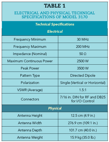
Recognizing the need for innovation, ETS-Lindgren has introduced the Model 3170 Intell-I-Tune™ Antenna System. Designed to replace the traditional biconical antenna, the Intell-I-Tune system integrates tunable dipole technology with automated control. It delivers the performance required for RS103 testing while reducing strain on amplifiers and improving overall efficiency. Table 1 shows the technical specifications, including electrical and physical characteristics.
For facilities facing the challenges of RS103, the Intell-I-Tune system represents a practical, forward-looking solution. It embodies the shift from legacy designs to smarter, adaptive technologies that meet the demands of modern military and aerospace testing.
ETS-Lindgren
Cedar Park, Texas
www.ets-lindgren.com