
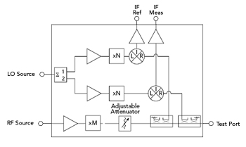
Figure 1 Typical architecture of Tx/Rx VNA frequency extender.
Increasing applications of mmWave technology are driving demand for higher frequency testing. With 3GPP frequency range 2 spectrum now extended up to 71 GHz, and 6G research exploring frequencies up to 175 GHz and beyond into the sub-THz range, there is a growing need for band-specific measurements such as over-the-air (OTA) characterization, antenna pattern measurement and S-parameter testing of components. The increasing development of mmWave and sub-THz application-specific integrated circuits has further intensified the demand for probe testing and on-wafer measurements. Applications such as E-Band automotive radar (76 to 81 GHz), satellite communication links from 71 to 86 GHz, wireless backhaul and fixed-wireless access in urban networks that leverage the E-Band demonstrate a growing need for mmWave band-specific testing.
Since the majority of commercially available vector network analyzers (VNAs) typically operate up to a maximum frequency of 50 GHz, frequency extension modules are essential for characterizing devices beyond the instrument’s native range. A pair of VNA frequency extender transceiver modules enables full two-port S-parameter measurements. As shown schematically in Figure 1, each extender transceiver (Tx/Rx) receives a local oscillator (LO) input from the VNA, which is split into two channels to drive individual receivers. The transmit path multiplies the VNA test-port signal to the target mmWave frequency, while a fixed offset between the two VNA ports generates a constant intermediate frequency (IF). The forward-coupled transmit signal provides an IF reference back to the VNA for amplitude and phase calibration, and the measurement receiver returns an IF signal representing the device under test (DUT) response. When used as a calibrated pair, these transceiver modules enable measurement of all four S-parameters across extended mmWave and sub-THz frequency bands.
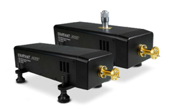
Figure 2 WR-10 ACCESS extender set with and without adjustable attenuators.
Over the past few years, Eravant has successfully demonstrated its first-generation VNA extenders, designed with in-house discrete off-the-shelf components and covering the 20 to 330 GHz frequency range. Building on this foundation and responding to the expanding mmWave application landscape, the focus for the next generation extender line shifted toward performance optimization and manufacturing efficiency. To achieve this, Eravant developed proprietary integrated circuits that replaced various building blocks in RF assemblies with only a few integrated multifunction components. This design-for-manufacturing initiative led to the creation of the ACCESS Series VNA Extenders, as shown in Figure 2.
The result was a reduction in material and labor costs, streamlined assembly and a lighter supply chain load. This effort also delivered measurable technical performance improvements. The new proprietary chipsets underwent extensive qualification to ensure long-term reliability, amplitude stability and phase stability. ACCESS series extender heads maintain stable temperature over prolonged usage, which ensures long-term repeatable measurement without frequent recalibration. Furthermore, the ACCESS extenders for V-, E- and W-Bands provide up to 15 percent wider frequency coverage than their predecessors, which only cover the full waveguide bandwidth. Mechanical refinements, including a length reduction from 11.5 to 8 in. and a weight reduction from 4.4 to 2.8 lb., make these extenders ideal for space-constrained setups, such as gimbal-mounted OTA chambers and on-wafer probe testing.

Table 1 shows the complete lineup of base ACCESS series VNA extenders. The -CM-E2 versions include an optional adjustable-level attenuator that provides up to 30 dB of output power control, making it valuable for testing input-power-sensitive devices such as LNAs and power amplifiers. Each extender module includes 1 in. and 2.5 in. waveguide straight sections featuring Eravant’s Proxi-Flange™ contactless interface. By incorporating this flange section, setup and calibration time for two-port calibrations, such as short-open-load-thru and thru-reflect-line, can be reduced significantly because there is no need to manually tighten waveguide screws and worry about flange misalignment. This feature also improves measurement repeatability and reliability as the screwless measurements prevent the risk of cross-threading and mechanical wear that could potentially compromise calibration accuracy at mmWave and sub-THz frequencies. Each extender ships with a test report including measurements like test port output power, dynamic range and calibration certificate, ensuring full specification compliance. These reports are stored in a USB memory which can be accessed via the USB-C port provided on the rear panel of the extender head. Performance of the WR-10 ACCESS VNA extender over 67 to 116 GHz is shown in Figure 3.

Figure 3 ACCESS VNA Extender’s measured dynamic range and output power.

Figure 4 Miniature extender architecture, Tx/Ref (a) and Rx (b).
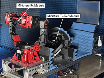
Figure 5 VNA extender setup using open-bed CATR.
Compact form-factor of the ACCESS series extenders can be further tailored for OTA testing applications, where one-directional measurement, such as gain and radiation pattern characterization, does not require full-duplex extender heads. A miniaturized set consisting of a transmit reference (Tx/Ref) module and a receive (Rx) module can be developed simply by reducing the number of components in the current ACCESS extender RF chain, as illustrated in Figure 4. This further reduction in size and weight enables easier integration on gimbals while preserving the gimbal’s payload capacity for the DUT, which makes this configuration ideal for open-bed mmWave compact antenna test range (CATR) setups. Figure 5 shows the VNA extender setup measuring 110 to 170 GHz using open-bed CATR.
While passive component testing generally requires only moderate output power, many advanced applications demand VNA extenders with higher test port power to overcome signal loss and enable accurate characterization. High-output extenders are useful for applications such as on-wafer measurements, OTA antenna testing and sub-THz material characterization, where path losses and setup attenuation dictate stronger test port output power in order to maintain sufficient drive power and dynamic range. In the future, current base ACCESS extenders can be upgraded with high test port output power by adding a power amplification stage on the transmit path.
The Next Generation ACCESS Series VNA Extenders feature a compact, high performance and thermally stable architecture designed with cost efficiency in mind. This initiative aims to reduce the traditional barriers to entry in mmWave developments. As demand for higher frequency characterization continues to expand across 6G, automotive radar, satellite communications and other emerging applications, Eravant’s ACCESS platform reflects the company’s mission to make mmWave technology more accessible, empowering engineers and innovators to advance the next generation of high frequency systems.
Eravant (formerly Sage Millimeter Inc.)
Torrance, Calif.
www.eravant.com