
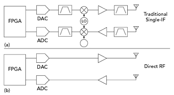
Figure 1 (a) Single-IF vs. (b) Direct RF system.
Modern communication, sensing, radar and electronic warfare (EW) systems increasingly require the ability to process wide instantaneous bandwidths (IBW) and support highly agile, multi-band operation. These demands are driving rapid advancement in high speed data converter technology, with analogue-to-digital converters (ADCs) and digital-to-analogue converters (DACs) pushing to higher sampling rates and wider input bandwidths. At the same time, semiconductor manufacturers are extending the RF input bandwidths of these converters into the microwave range and beyond, allowing radio signals to be digitised at or near their carrier frequencies. Systems that exploit these capabilities are referred to as Direct RF architectures.
In a traditional heterodyne radio receiver, the RF signal is translated to a lower intermediate frequency (IF) using mixers and local oscillators, then it is filtered and digitised. In contrast, a Direct RF approach digitises the incoming RF signal directly, potentially eliminating most of the analogue signal processing chain. The analogue frequency translation that typically occurs in mixers is replaced by digital down-conversion (DDC) within the ADC or digital up-converter (DUC) contained within the DAC.

Figure 2 Receiver example of a single-IF vs. a Direct RF system mixing process.
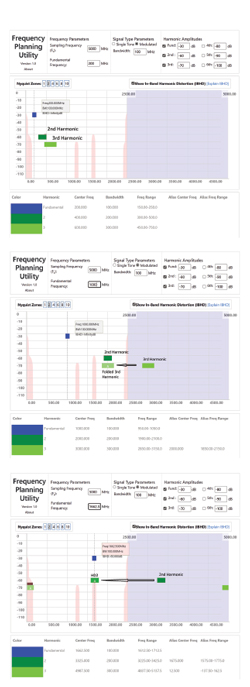
Figure 3 5 GSPS ADC with a 100 MHz wide wanted signal.
The key motivation behind Direct RF is system simplification and software-driven adaptability. With fewer analogue stages, the radio becomes more compact, easier to calibrate and more repeatable from unit to unit. Digital processing provides reconfigurability with centre frequency, bandwidth, filtering and channelisation being determined through software/firmware rather than fixed analogue hardware.
Direct RF does not, however, eliminate all RF hardware considerations. Challenges arise from multiple sources, such as sampling-based spurious artefacts, clock distribution, dynamic range limitations of ADCs and transmit power amplifier (PA) efficiency. Practical RF filtering and front-end matching networks remain essential. Therefore, while Direct RF reduces analogue complexity and alleviates some classical RF engineering problems, it creates new system behaviour that requires careful analysis and design.
The following sections provide a detailed overview of Direct RF system operation, current converter technology, advantages and trade-offs and future expected developments in RF front-end architectures.
PRINCIPLES OF DIRECT RF SAMPLING
Conventional Versus Direct RF Architectures
Figure 1 illustrates a simplified comparison of a single-IF heterodyne system and a Direct RF system. Figure 2 provides an associated receiver frequency plan for these two cases. In a traditional heterodyne system, the input signal at RF is mixed to an IF frequency located well within the analogue bandwidth of the ADC. The ADC sampling rate is typically selected to be at least 2.5x the signal bandwidth to support digital processing without aliasing. The mixer and LO define where the signal resides in the spectrum prior to digitisation.
In a Direct RF system, the analogue mixing stage is removed entirely. The RF signal is sampled directly, and digital frequency translation (DDC in the case of a receiver) moves the signal to baseband. The sampling rate must therefore be greater than 2.5x the carrier frequency of the RF signal, rather than only exceeding the signal bandwidth. For example, to digitise a 200 MHz wide signal at 3 GHz, a sampling rate of at least around 7.5 GSPS is required, with higher values preferred to avoid in-band spurious folding.
Analog Devices provides a frequency folding tool, which is useful for visualising spurious sampling products.1 The main spurious products of concern are HD2 and HD3. These products are generated by the second and third harmonic of the input signal mixing with the sample clock in the converter. Figure 3 shows an example of a 5 GSPS sample rate ADC with 100 MHz IBW signal for 200 MHz, 1000 MHz and 1662.5 MHz input frequencies, with plots produced from an AD frequency folding tool.1 In the 200 MHz input signal case, the harmonics of the input signal can be seen to lie within the first Nyquist zone. As the input frequency is increased to 1 GHz, the third harmonic product is folded around Fs/2 into the first Nyquist zone (labelled HD3). As the input frequency is increased further, the second harmonic folds around Fs/2 and appears in-band as HD2. The pink areas show the input frequencies at which in-band spurious products will appear. In this case, where the input signal IBW is significantly less than the sample rate, there are many input frequencies available with no in-band sampling product-based spurious (up to third order). The matter of sample rate choice and associated maximum IBW will be discussed later in this article.
Notably, the ratio of signal bandwidth to sampling frequency determines spur-free frequency regions. If the signal bandwidth is narrow relative to the sampling frequency, there are many spur-free centre frequency options. If the signal bandwidth increases, spur-free regions diminish rapidly, as discussed later in this article.
Current State of High Speed Data Converters
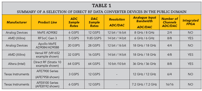
Direct RF operation has become feasible due to advances in high speed mixed-signal ICs, multi-core sampling architectures and integrated DSP blocks. Some representative high performance platforms are highlighted in Table 1.
There are multiple suppliers who use these devices in higher-level modules and systems, such as Mercury Systems, Avnet, Annapolis, Slipstream, Enclustra and Trenz.
Example Deployment: Slipstream Design’s ASTRO RFSoC SOM
Slipstream Design’s ASTRO RF system-on-module (SOM) utilises the AMD Gen3 RFSoC, which integrates the Direct RF converters with a powerful on-board Zynq FPGA and quad ARM processors. The SOM integrates 8 x 5 GSPS 14 bit ADCs and 8 x 10 GSPS 14 bit DACs onto a compact 94 x 69 mm module. Figure 4 shows the module that features on-board sample clock support. This type of module demonstrates how Direct RF capability can now be delivered in compact embedded form factors, suitable for airborne, unmanned and distributed RF sensing applications.
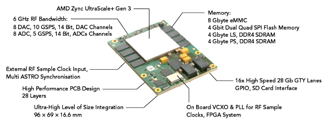
Figure 4 Slipstream Design’s ASTRO RFSoC SOM.
ADVANTAGES OF THE DIRECT RF APPROACH
Reconfigurability Through Software
Digital LO (numerically controlled oscillator (NCO)) tuning and baseband filter reconfiguration allow agile multi-band operation without changing analogue hardware. This is particularly beneficial in adaptive radar, EW, multi-mission radios and dynamic spectrum systems.
Reduction in Analogue Hardware
Eliminating mixers, LO distribution networks and IF filters reduces size and weight, minimises temperature and aging-related variation and improves unit-to-unit reproducibility.