Simplified Calibration
Digital calibration loops and numerically defined signal chains offer deterministic phase and gain characteristics. Unlike analogue networks, there is no tuning required during manufacture or deployment.
Ease of Channelisation
Wideband receive data can be digitally channelised into multiple sub-bands efficiently, using polyphase filter banks or FFT-based channelisers.
CHALLENGES IN DEPLOYING DIRECT RF SYSTEMS
Although Direct RF has many benefits, there still exist challenges that require a combination of software, firmware and RF hardware capabilities and skill sets to overcome. For example, some challenges include:
Spur-Free Operating Window Versus Bandwidth
Continuing the receiver example from earlier, as illustrated in Figure 5, increasing the input IBW from 100 to 400 MHz dramatically reduces the number of spur-free centre frequency regions when using a 5 GSPS ADC. The designer is left with only one or two usable input frequency windows, depending on which Nyquist zone they choose. This means that the system designer who wanted a flexible input frequency range would need to consider either an external mixer or increasing the sample rate of the data converters to widen the spur-free zone and restore flexibility of centre frequency, as demonstrated in Figure 6. However, increasing the sample rate comes with trade-offs:
- Higher sampling rates increase converter and FPGA power consumption.
- Multi-core interleaving introduces additional calibration requirements to suppress interleaving spurs.
- Higher clock rates increase clock jitter demands.
Increasing sample rates remains one of the central engineering trade-offs in Direct RF systems.
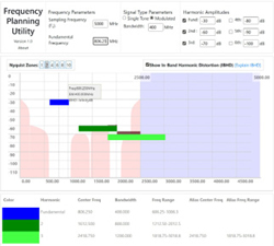
Figure 5 A 400 MHz IBW signal with a 5 GSPS sample rate.
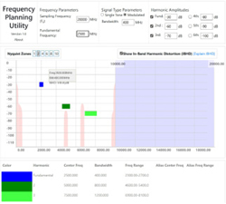
Figure 6 A 400 MHz IBW signal with a 20 GSPS sample rate.
Out-of-Band Interference and ADC Saturation
A key dynamic range metric is the difference between IIP3 and noise figure.2 For a high performing ADC such as the AD9082, a greater than 10 dB difference between IIP3 (35.8 dBm) and noise figure (25 dB) is achieved. It is possible to achieve slightly better results with a high performing heterodyne solution using, for example, a mixer like the Marki Microwave MT3-0113HCQG-2. With high performing solutions, it is possible to achieve a 19 dB difference between IIP3 and noise figure (29 dBm IIP3 and 10 dB NF). That said, the performance differential of pure dynamic range is not hugely significant.
For receivers, the significant metric is the maximum input signal. Typically, most Direct RF ADCs will have a full-scale input power of around +5 dBm. Without appropriate filtering, high-power out-of-band interferers can result in this level being exceeded anywhere in the band of operation, resulting in saturation of the ADC and temporary failure of the entire receiver band. Providing narrowband and low loss, tunable filtering that can track the RF input signal in Direct RF applications is challenging, particularly in a small form factor, and is the subject of much current research.
This is where heterodyne solutions have an advantage, as they can leverage the fixed-frequency IF filter to reject out-of-band signals. Because the IF filter is fixed in frequency, it can be highly optimised for the bandwidth of operation. Although the mixer will generate spurs as a result of high level out-of-band interferers, it will not cease to function, as is the case with ADC saturation. It is also typical to see systems with switchable IF filters in heterodyne solutions to accommodate different signal bandwidths.
Transmit PA Efficiency
An often overlooked challenge in the context of Direct RF (transmit side) is the ability to generate the high RF signal levels suitable for transmission in practical systems in a power-efficient manner over a wide RF bandwidth. Although Direct RF DACs can flexibly generate a wide range of output frequencies, typically, PAs have poor power-added efficiency (PAE) when operating in backed-off modes and over wide frequency ranges. The Analog Devices ADPA1113 2 to 6 GHz 40 W GaN PA, for example, has a peak PAE of around 30 percent over this bandwidth. A narrowband (< 200 MHz) PA in this frequency range would be expected to have a peak efficiency of greater than 65 percent. This demonstrates the need for reconfigurable and digitally adaptable PA technology. Adaptive PA architectures, including load-modulated balanced amplifiers (LMBA) and wideband Doherty structures, are likely to become critical in future Direct RF systems.
Channel Synchronisation Across Many Converters
Another key challenge with high sample rate Direct RF data converters is the requirement for multiple sample clocks to be synchronised. This challenge exists where more than one ADC or DAC is required to operate in a coherent manner. An example of this is a phased array application where many elements must operate coherently with each other to form a beam. In a traditional heterodyne system, this is less problematic because the local oscillator can be distributed to every element, and notwithstanding practical routing problems, this automatically provides coherence across all elements. Since the heterodyne approach uses much lower sample rate ADCs, synchronisation of these clocks is far less of a challenge.
With the high sample rates of Direct RF converters and the associated digital circuitry (such as FIFOs) that sit between the point of sampling and the resulting data stream, synchronisation across multiple Direct RF converters is a key technical challenge. Typically, achieving synchronisation across multiple converters requires a combination of using vendor-supplied synchronisation schemes, custom clock distribution hardware and custom-implemented digital equalisation filtering. This requires a range of different engineering disciplines, from RF to software and firmware, to implement. Figure 7 shows measured data of four different Slipstream Design ASTRO DAC channels. Figure 7a shows the DAC outputs prior to synchronisation, Figure 7b shows the data with the AMD Multi-Tile Synchronisation (MTS) applied and Figure 7c shows the result with custom digitally applied equalisation filters to remove the effects of RF tracking and cables following a calibration process. Figure 7 shows measured improvements demonstrating progressive synchronisation refinement.

Figure 7 Synchronisation of an ASTRO RFSoC with (a) DAC outputs before synchronisation, (b) MTS and (c) with equalisation filters.
FUTURE CIRCUITRY TO SUPPORT DIRECT RF
The trend of Direct RF converters is likely to continue with IBW and RF input frequency continuing to increase. Although such devices promise extreme flexibility and software reconfigurability, they will not eliminate the need for RF components between the antenna and the data converters.
At the most basic level, typical interfaces to data converters are differential, requiring a balun. The wideband nature of Direct RF converters is driving a move towards single-ended interfaces using wideband on-chip differential amplifiers.
It is expected that in many applications, including wideband systems operating in relatively harsh electromagnetic environments, systems will continue to use a single stage of external frequency conversion (mixer + LO) to bring the required IBW down to a fixed location in the data converters’ Nyquist zone. This approach is likely to provide the most robust solution for rejecting out-of-band interferers and managing spurs. Until low loss narrowband tunable filters become a reality, this will likely remain a relatively common architecture, with the high sample rate of the data converters enabling the high signal IBW. External frequency converters also serve to extend the frequency range of the data converters, making them difficult to obsolete. It is expected that, where an external mixer cannot be used, switched filter banks will remain critically important to manage harmonics and spurs. The design of such functionality requires a high level of RF engineering skill.
It is expected that reconfigurable and adaptable PAs, such as LMBAs, will be essential RF hardware in future Direct RF systems, allowing the flexibility of these systems to be reflected in practical implementations.
The digital techniques and RF hardware associated with high sample rate multiple converter synchronisation and clocking will be a key technology and engineering discipline for the successful uptake of Direct RF, particularly in systems that require many coherent elements.
RF PERSONALITY MODULES
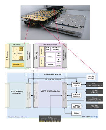
Figure 8 ASTRO Nova (PCIe) concept.
Reflecting on the continued need for application-specific RF circuitry that sits between the converters and the antenna, Slipstream Design has adopted a modular approach, pairing high speed converter modules with RF personality modules. These personality modules allow the same converter core to be adapted to different missions or frequency requirements without redesign of the underlying digital platform. Figure 8 shows ASTRO Nova (PCIe), which features the 8-channel ASTRO RFSoC SOM (8 DAC/8 ADC) module fitted to a PCIe carrier with an RF personality card that sits between the converters and the RF ports.
CONCLUSION
Direct RF technology has evolved from a research concept into deployment-ready system architectures, driven by innovations in high speed converters and integrated digital processing. The advantages, including reduced analogue complexity, software-driven reconfigurability, compact implementation and manufacturing repeatability, are substantial and increasingly attractive across radar, EW, satcom and multi-band communications.
However, system designers must be aware of the non-ideal factors, including the relationship between IBW and sampling rate, spur management, limitations in ADC full-scale handling of out-of-band interferers, PA efficiency constraints and synchronisation across multi-channel systems. These challenges do not limit the applicability of Direct RF, but they do shape the necessary RF front-end architectures that accompany it.
Future Direct RF systems are likely to pair high speed converters with adaptive filtering, reconfigurable up-/down-conversion modules and digitally configurable PA architectures. The result will be radio systems that combine the flexibility of software-defined waveforms with the practical RF performance needed in real operational environments.
In summary, modern radio systems demand a combination of RF, digital design, firmware, system architecture, thermal and packaging expertise. While more of the signal chain has shifted into the digital domain, the RF challenges have not disappeared; they have simply changed in nature!
References
- Frequency Folding Tool, Analog.com, 2025, Web: https://tools.analog.com/en/toolbox/FreqFolding/.
- W. Taylor, “Considering GSPS ADCs in RF Systems,” Analog.com and Analog Devices, Inc., November, 2021, Web: https://www.analog.com/en/resources/technical-articles/considering-gsps-adcs-in-rf-systems.html?utm_source=chatgpt.com.