

Power dividers are passive microwave components used in microwave systems to proportionally distribute power from a microwave source to antenna array elements.1 The radiation efficiency of high-power microwave systems is greatly impacted by power divider performance. Parameters used to measure performance include return loss, insertion loss, power handling capability (PHC), amplitude and phase imbalance, bandwidth and isolation.2
The waveguide-based power divider (PD) stands out for its high PHC, low insertion loss and wide bandwidth when compared with planar microstrip structures. This makes it a popular choice for high-power microwave systems.3
Waveguide PDs can be classified into several categories depending on the architecture, such as T-junction,4,5 Magic-T,6-8 ridge waveguide,9,10 Riblet-type,11,12 Gysel structure9-13 and branch guide.14-15 In practice, each has its advantages, disadvantages and limitations.
Waveguide T-junctions feature simple structures and are easy to design; however, matching and isolation between output ports are poor. Magic-T PDs demonstrate enhanced impedance matching and port isolation; however, the four waveguide arms of the conventional Magic-T are in the E- and H-planes, creating more difficult assembly and fabrication processes.
In recent years, coplanar waveguide Magic-Ts based on transition structures have been investigated. Ameri et al.8 introduced a broadband and low loss E-plane waveguide Magic-T incorporating an innovative air-filled self-suspended rectangular-to-coaxial transmission line to interface the sum port of the Magic-T with the T-junction. This structure provided a higher PHC compared to a Magic-T microstrip probe, reaching up to 20 kW.
The Magic-T structure features a single isolated port, whereas the waveguide Gysel PD offers two isolated ports, which is more desirable in practical applications. Fahmi et al.9 described two different designs of ridge waveguide Gysel PDs for E-plane and H-plane configurations that combine the advantages of ridge waveguide and Gysel types to achieve a compact size, wider bandwidth and good PHC. The E-plane-aligned design provides better PHC through a vertically stacked arrangement of ridge waveguides, and simulated results show a PHC of around 50 kW across the operating range.
These designs successfully achieve high isolation, a broad bandwidth and a compact size. However, limited PHC makes them inappropriate for use in high-power systems. To obtain high PHC and good transmission efficiency, the four-way equal PD described in this work is based on a dielectric window. It is designed to operate in the C-Band.
To enhance its PHC, the T-junction connected to the microwave source is vacuum sealed, since the breakdown field strength in a vacuum substantially exceeds that in air. An ‘I’-shaped dielectric window with low loss organic materials is used for sealing. Furthermore, to feed an array antenna with the circular waveguide TM01 mode, a TE10 to TM01 mode converter is designed and integrated into the PD output.
ANALYSIS AND DESIGN
The PD comprises three components: T-junction, dielectric window and mode converter. These are individually designed and characterized, and are then integrated and optimized.
T-Junction PD
The T-junction is the fundamental component, shown in Figure 1. A four-way PD is constructed by cascading three T-junctions. The interior of the T-junction PD is vacuum sealed at a high atmospheric pressure. To avoid deformation of rectangular waveguide edges due to the pressure difference, a circular waveguide with better pressure resistance is used at the output. The larger cross-sectional area of a circular waveguide also permits microwave energy to be distributed more uniformly.
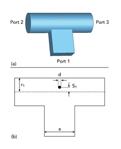
Figure 1 T-junction PD structure: 3D view (a) and longitudinal cross-section (b).
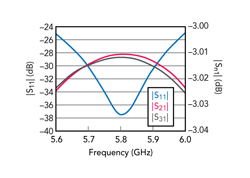
Figure 2 T-junction PD simulated S-parameters.
Theoretical analysis shows that the T-junction without a modulator results in high reflections and low energy transfer efficiency.16 Hence, a metal post is added at the waveguide junction to improve matching performance and extend the bandwidth. Power distribution is influenced by the position of the metal post. To achieve equal power division, the matching post is positioned along the center line of the wide edge of the input rectangular waveguide. Excellent performance is obtained by adjusting the diameter d of the metal post and the distance S1 of the post from the center. Electromagnetic simulation software is employed to optimize the design until |S11| is below -20 dB, as demonstrated in Figure 2. The transmission coefficients of the two output ports are around -3 dB, achieving equal power distribution.
Dielectric Window
The dielectric window acts as a barrier between the vacuum and the atmosphere while ensuring maximum power transmission. Based on the shape, dielectric windows can be classified into categories such as pillbox windows, rectangular windows and coaxial windows. Among these, the pillbox window is widely used in microwave vacuum electronic devices due to its simple structure, high PHC, wide operating bandwidth and mature fabrication process.17,18
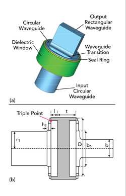
Figure 3 Dielectric window structure: 3D view (a) and longitudinal cross-section (b).
In this work, low loss polyethylene with a dielectric constant of 2.0 is used as the window material. Since organic materials cannot be fixed by welding, a groove in the waveguide wall is required to secure the window disk into a conventional pillbox window, which can easily lead to an increase in field strength at the triple point (vacuum-dielectric-metal junction — see Figure 3).
To address this, the conventional pillbox window structure is improved; the edge of the window disk is designed to protrude outward with a specific thickness and extends longitudinally to match the length of the circular waveguide. As a result, the longitudinal cross-section of the window from the “|” is transformed into an “I” shape. The “I”-shaped dielectric window is secured with a sealing ring, which does not affect the field distribution on the surface of the dielectric window.
The “I”-shaped structural design can maintain a certain height between the triple point and the window surface, making it difficult for electrons emitted from the triple point to travel to the window surface, thereby suppressing secondary electron multiplication and effectively avoiding flashover breakdown of the dielectric window.
The dielectric window assembly contains the input and output rectangular waveguide sections, waveguide transition section, circular waveguide section and dielectric window, as shown in Figure 3. The window diameter is typically chosen to be equal to the length of the input or output rectangular waveguide diagonal.19 The diagonal length of the standard BJ48 rectangular waveguide is approximately 52.5 mm.
To further reduce the window’s surface field strength, the diameter of the dielectric window is increased to operate in an over-mode condition. The initial diameter of the window disk is selected to be 70 mm, and a rectangular transition waveguide is employed to control higher-order modes in the structure. The thickness of the window disk is half the waveguide wavelength of the filling medium to withstand the pressure difference between the vacuum and the gas.
The structural dimensions obtained from initial calculations are optimized. Figure 4 shows the simulation results. |S11| is below -20 dB across the 400 MHz bandwidth, while the surface electric field exhibits a well-defined TE11 mode distribution; the field strength is maximum in the center of the window disk and decreases toward the edge.
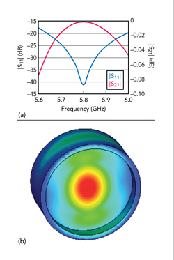
Figure 4 Simulated optimized dielectric window S-parameters (a) and field distribution at the window surface (b).
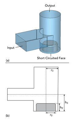
Figure 5 TE10-to-TM01 mode converter structure: 3D view (a) and longitudinal cross-section (b).
TE10-to-TM01 Mode Converter
The mode converter produces a desired output mode for propagation. In a radial line antenna array system, the PD network and antenna array are in parallel planes; thus, the microwave path must be turned 90 degrees. For this purpose, a TE10-to-TM01 mode converter within a right-angled structure is designed, as demonstrated in Figure 5.
The mode converter comprises a circular waveguide section with a short-circuit termination and an orthogonally intersecting rectangular waveguide. The orthogonal intersection of the two waveguides is the mode-conversion region. Electromagnetic waves entering through the rectangular waveguide generate a transmitted component propagating in the negative direction along the circular waveguide. By setting the length of the short-circuit section to half the guide wavelength, the electric field is reflected at the shorting plate to the output. A metal cylindrical tuning screw is incorporated at the shorting plate to adjust matching and increase the bandwidth.
In the mode-conversion region, higher-order modes may be generated due to structural discontinuities. Mode control is performed by selecting a suitable circular waveguide diameter. The condition for transmitting the TM01 mode while suppressing TE21 and other higher modes in a circular waveguide can be derived with Equation 1.

Where α is the radius of the circular waveguide.
The short-circuited section with the added matching screw can be considered a coaxial waveguide, transmitting TEM waves with a phase velocity essentially equal to the speed of light. Consequently, the short-circuited segment is equivalently composed of a circular waveguide and a coaxial waveguide. To achieve single-port output, this composite structure must still satisfy the half-wavelength condition of the equivalent waveguide. The lengths of the coaxial and circular waveguide sections are calculated separately, adhering to the relationship in Equation 2.20
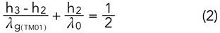
Where h3 is the total length of the short-circuited section and h2 is the height of the tuning screw.