
By adjusting the values of h2 and h3, a high mode-conversion efficiency is achieved, as shown in Figure 6. Figure 6a shows good matching performance with transmission efficiency exceeding 99 percent within the operating bandwidth. Figure 6b shows the field distribution. The axial field pattern confirms that a TM01 mode is successfully formed at the converter output.
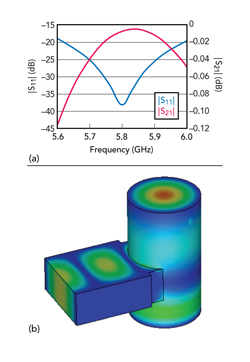
Figure 6 Simulated mode converter S-parameters (a) and field distribution (b).
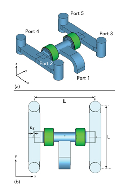
Figure 7 PD configuration: 3D view (a) and top view (b).
FOUR-WAY PD SIMULATION AND OPTIMIZATION
Figure 7 shows the overall structure of the four-way PD. The input power from Port 1 is initially split into two equal-amplitude signals through the primary T-junction. These divided signals are subsequently further divided into four outputs by two more T-junctions after transmission through a dielectric window. Finally, the rectangular waveguide output TE10 mode is converted into the circular TM01 mode via mode converters. The input side of the dielectric window is maintained under vacuum, while the output side is filled with SF6 gas at a specified pressure and concentration.
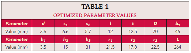
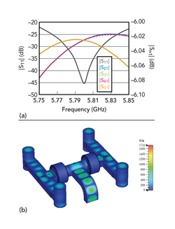
Figure 8 Four-way PD simulated S-parameters (a) and field distribution (b).
To achieve optimal performance, parameters that affect the matching performance of the four-way PD are analyzed. Excellent performance is achieved by adjusting the metal post locations s1 and s2 in the two-stage cascaded T-junctions. Optimized parameter dimensions are listed in Table 1.
Simulated S-parameters are plotted in Figure 8a. |S11| is below -22 dB over the operating band and is less than -45 dB at the center frequency. Transmission coefficients are greater than -6.1 dB across the band. Considering that the theoretical distribution loss for a four-way PD is 6 dB, the simulated insertion loss is below 0.1 dB.
The simulation demonstrates equal power division with an amplitude imbalance of less than 0.05 dB. The maximum electric field strength is 1733 V/m (see Figure 8b), which occurs in the vacuum region. When the input power is 0.5 W, the PHC can be calculated using Equation 3.
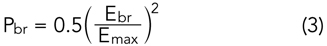
Based on the vacuum breakdown threshold of 20 MV/m, the calculated PHC reaches 66.59 MW in the vacuum section. The overall PHC of the system is limited by the dielectric window. The maximum value of the electric field of the dielectric window is simulated to be 561 V/m. Assuming a breakdown threshold of 6 MV/m for polyethylene, the derived PHC for the window is 57.2 MW. Similarly, the power capacity of the mode converter is calculated to be 82.8 MW. Therefore, the four-way PD’s overall PHC is as high as 57.2 MW.
MEASUREMENTS
A prototype four-way PD, as shown in Figure 9, is measured with a vector network analyzer. One coaxial-to-rectangular waveguide and four coaxial-to-circular waveguide adapters are used to connect the ports for testing.
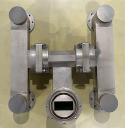
Figure 9 Prototype four-way power divider.
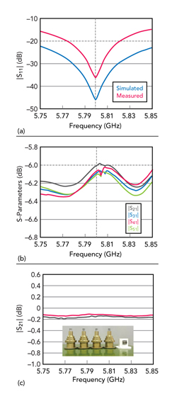
Figure 10 Measured and simulated |S11| (a), measured transmission coefficients (b) and measured insertion loss of the adapters (c).
Measured and simulated |S11| are compared in Figure 10a. Measured values are better than -15 dB within the operating band. At the center frequency, |S11| is less than -35 dB. Measured results are uniformly higher, which may be due to errors in manufacturing, assembly and measurement. Considering that waveguide converters and matched loads are used in testing, the effects of non-ideal contacts and mismatches are unavoidable.
The measured transmission coefficients of the four-way PD, as seen in Figure 10b, are greater than -6.35 dB across the operational frequency range. In the measurement process, rectangular-to-coaxial and circular-to-coaxial waveguide converters employed for testing introduce additional insertion loss. The intrinsic insertion loss of the four-way PD is determined by subtracting the insertion losses of both converters from the total measured value.
Figure 10c shows the insertion loss results obtained through back-to-back measurements of two identical converters, from which the insertion loss of a single coaxial-to-rectangular waveguide converter is estimated to be approximately 0.10 dB, while that of a single coaxial-circular waveguide converter is approximately 0.07 dB. After compensating for the waveguide converter losses, the PD exhibits a low insertion loss of less than 0.2 dB. In addition, it demonstrates excellent amplitude imbalance within ± 0.1 dB at the designed frequency.
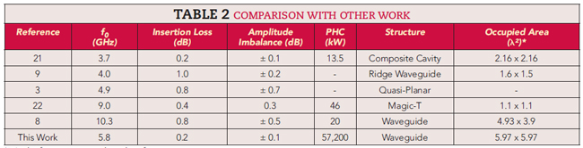
The characteristics and performance of this design are compared with other work in Table 2. This design provides a combination of higher PHC, lower insertion loss and better amplitude balance.
CONCLUSION
A C-Band four-way equal PD with a dielectric window provides high PHC, low loss and excellent amplitude balance. By evacuating the interior of the input T-junction and sealing it with low loss material dielectric windows, PHC is significantly enhanced. A mode converter enables the PD to produce a TM01 mode output, facilitating connection to the next structure. Simulation demonstrates MW-level PHC with low loss and superior amplitude balance.
ACKNOWLEDGMENT
This work was supported in part by the Fundamental Research Funds for the Central Universities under Grant 2682024GF013.
References
- C. A. Sreejith, M. Tamang and K. S. Beenamole, “High Power Ratio Waveguide Power Divider,” IEEE Microwaves, Antennas, and Propagation Conference, December 2022.
- O. Wossugieniri, H. Faezi and M. Fallah, “Compact 2-Way H-Plane Power Dividers for a Rectangular Waveguide in Ku Band,” 22nd International Microwave and Radar Conference, May 2018.
- K. J. Song, S. Y. Hu, F. Zhang and Y. Zhu, “Four-Way Chained Quasi-Planar Power Divider Using Rectangular Coaxial Waveguide,” IEEE Microwave and Wireless Components Letters, Vol. 25, No. 6, June 2015, pp. 373–375.
- Z. Xu, J. Xu, Y. Cui and C. Qian, “A Novel Rectangular Waveguide T-Junction for Power Combining Application,” IEEE Microwave and Wireless Components Letters, Vol. 25, No. 8, August 2015, pp. 529–531.
- B. Wang, B. Tian and C. -T. Wang, “Power Divider/Combiner of Waveguide E-T Junction Based on Thin Film Resistor,” Journal of Infrared and Millimeter Waves, Vol. 36, No. 1, February 2017.
- R. Vincenti Gatti, R. Rossi, M. Dionigi and A. Spigarelli, “An X‐Band Compact and Low‐Profile Waveguide Magic‐T,” International Journal of RF and Microwave Computer‐Aided Engineering, Vol. 29, No. 9, May 2019.
- E. Ameri, M. Khalaj‐Amirhosseini, S. H. Sedighy and Yousef Azizi, “Design of New Wideband Waveguide Magic‐T for X‐Band Applications,” Microwave and Optical Technology Letters, Vol. 65, No. 9, May 2023, pp. 2530–2534.
- C. Guo, J. Li, Yang Yu, F. Zhang, Y. Zhu, Q. Yang, W. Zhu, S. Zhu, X. Shang, Y. Gao, Y. Wang, G. -L. Huang, Q. S. Cheng and A. Zhang, “A 3-D Printed E-Plane Waveguide Magic-T Using Air-Filled Coax-to-Waveguide Transitions,” IEEE Transactions on Microwave Theory and Techniques, Vol. 67, No. 12, December 2019, pp. 4984–4994.
- M. M. Fahmi, J. A. Ruiz-Cruz and R. R. Mansour, “Compact Ridge Waveguide Gysel Combiners for High-Power Applications,” IEEE Transactions on Microwave Theory and Techniques, Vol. 67, No. 3, March 2019, pp. 968–977.
- J. Wu, C. Wang and Y. Guo, “Ridged Waveguide Magic Tees Based on 3-D Printing Technology,” IEEE Transactions on Microwave Theory and Techniques, Vol. 68, No. 10, October 2020, pp. 4267–4275.
- G. A. Kumar, B. Biswas and D. R. Poddar, “A Compact Broadband Riblet-Type Three-Way Power Divider in Rectangular Waveguides,” IEEE Microwave and Wireless Components Letters, Vol. 27, No. 2, February 2017, pp. 141–143.
- K. Sharma, B. Biswas and S. K. Parui, “Design of a Compact Low Loss Four-Way Power Divider at W-Band,” 7th International Conference on Electronics, Materials Engineering & Nano-Technology, December 2023.
- K. Nobandegani and S. E. Hosseini, “Gysel Power Divider Realized by Ridge Gap Waveguide Technology,” IEEE Access, Vol. 9, May 2021, pp. 72103–72110.
- Y. Liu and B. Zhang, “The Design of 220 GHz Four-Way Power Divider Based on E-Plane Directional Waveguide Hybrid,” 14th UK-Europe-China Workshop on Millimetre-Waves and Terahertz Technologies, September 2021.
- J. Ding, Y. Zhao, J. -X. Ge and S. Shi, “A 90 Degree Waveguide Hybrid with Low Amplitude Imbalance in Full W-Band,” Journal of Infrared, Millimeter, and Terahertz Waves, Vol. 40, No. 4, April 2019, pp. 429–434.
- W. Lei, L. Li-hao and Y. Zhi-guo, “A Novel Power Splitter Based on the Waveguide E-Type T Junction,” Proceedings of the 5th Global Symposium on Millimeter-Waves, May 2012.
- S. Liu, “A RF Window for Broadband Millimeter Wave Tubes,” International Journal of Infrared and Millimeter Waves, Vol. 17, No. 1, January 1996, pp. 121–126.
- M. Cook, C. D. Joye, T. Kimura, E. L. Wright and J. P. Calame, “Broadband 220 GHz Vacuum Window for a Traveling Wave Tube Amplifier,” IEEE Transactions on Electron Devices, Vol. 60, No. 3, March 2013, pp. 1257–1259.
- Y. -G. Ding, “Theory and Computer Simulation of High Power Klystron,” National Defense Industry Press, Beijing, China, 2008, pp. 383–388.
- J. Zhang, Q. Liu, X. Li and Y. Liang, “A Compact TE11-TM01 Mode Converter for HPM Application,” Journal of Electromagnetic Waves and Applications, Vol. 32, No. 17, April 2018, pp. 2314–2320.
- Y. -X. Huang, Y. -X. Yan, Y. -J. Yang and J. -X. Chen, “Broadband Low-Loss Four-Way Power Divider Using Composite Cavity,” IEEE Microwave and Wireless Technology Letters, Vol. 34, No. 6, June 2024, pp. 595–598.
- L. Guo, J. Li, W. Huang, H. Shao and T. Ba, “A Compact Four-Way Power Combiner,” IEEE Microwave and Wireless Components Letters, Vol. 27, No. 3, March 2017, pp. 239–241.