
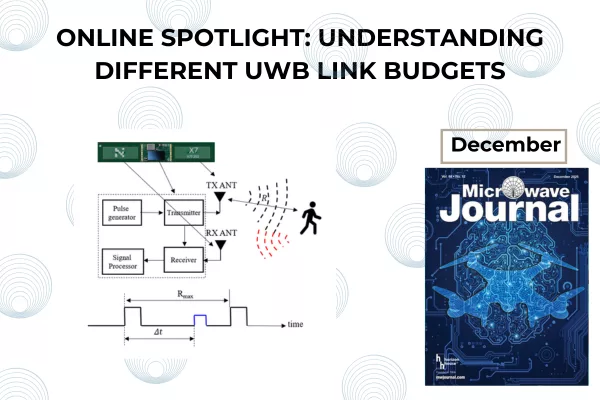
High-rate pulse repetition frequency ultra-wideband (HRP UWB) communication technology based on IEEE 802.15.4z embedded in smartphones measures the distance between two UWB devices and transmits information data through packet exchange. On the other hand, UWB radar measures the distance to surrounding objects and senses their movements by using the time difference between the transmitted pulse and the backscattered pulse. Data exchange between UWB devices, ranging of UWB devices and UWB radar sensing all have completely different operating principles but share the same local regulations worldwide. This article explains why the link budgets of the three technologies are different despite having the same local regulations. It also shows that it is important to balance the two links, the data link and the ranging link, in the case of UWB communication.
UWB technology, which is being used in various fields, does not refer to a single technology with a specific purpose, but refers to wireless technology with a bandwidth of 500 MHz or more. Legally, it refers to wireless technology that satisfies local regulations such as those listed in Table 1, although the frequency of operation is slightly different in each country.

UWB can be used for any purpose if it satisfies local regulations. Applications can be broadly divided into two categories: UWB wireless communication and UWB radar.1-4 Figure 1 shows some applications for UWB wireless communication and UWB radar technology, such as UWB smart tags for object location, UWB smart car keys, UWB real-time location service (RTLS) for asset tracking and UWB radar that detects the presence of a child in a vehicle.
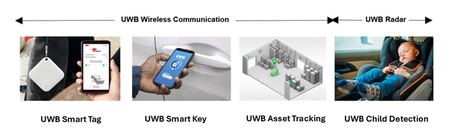
Figure 1 Various applications of UWB technology.
Unlike other wireless communication technologies such as Wi-Fi and Bluetooth, UWB wireless communication is characterized by having two functions at the same time: information transmission and distance measurement (ranging). There are various technologies in UWB wireless communication, but the currently commercialized technology is HRP UWB, which follows the IEEE 802.15.4z standard.5 It has been installed in most smartphones currently on sale since the service that informs the location of surrounding UWB devices was introduced in Apple's iPhone 11 in 2019. In addition, automobile companies such as Hyundai and BMW are introducing UWB smart keys. As such, HRP UWB communication is expected to find use in areas such as transportation, distribution, smart factories and smart homes.1,6
UWB radar is a pulse radar that measures the distance to objects around the radar, or it detects the movement of objects by using the time difference between the transmitted pulse and the pulse reflected from the target. A pulse radar’s range resolution is normally determined by and is inversely proportional to its pulse width, which in turn is inversely proportional to the pulse waveform bandwidth. A UWB radar is a high-resolution radar with a pulse waveform bandwidth of 500 MHz or more. A commercialized UWB radar is the UWB module provided by Novelda™. Novelda's UWBx4 module uses pulses with a bandwidth of 1.5 GHz (pulse width of approximately 0.67 nsec). Novelda's UWB radar is currently used in various fields such as human gestures and vehicle occupant recognition.4,7
UWB wireless communication and UWB radar have different operating principles, but they operate under the same local regulations worldwide. From the perspective of link analysis, it is necessary to understand how the two different technologies operate within the same rules. Since UWB communication technology includes two functions, information transmission and ranging, it is necessary to analyze how the two functions are integrated under the same regulations as well.
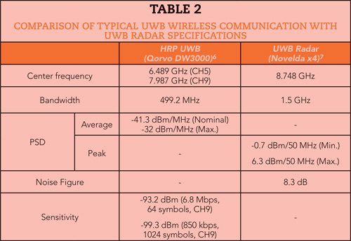
In this article, the operating principles of the two technologies are identified by referring to the currently commercialized IEEE 802.15.4z HRP UWB standard and Novelda’s UWB radar specification. Link budgets are analyzed using the Friis transmission formula and the radar range equation. Although various UWB wireless communication and UWB radar products are available on the market, this study is based on Qorvo’s DW3000 HRP UWB module6 and Novelda’s x4 UWB radar module,7 which are representative and widely used. Table 2 shows their main specifications. Figures 2 and 3 are photos of each product.
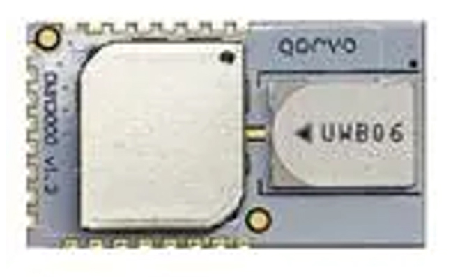
Figure 2 Qorvo’s DW3000 HRP UWB module.6
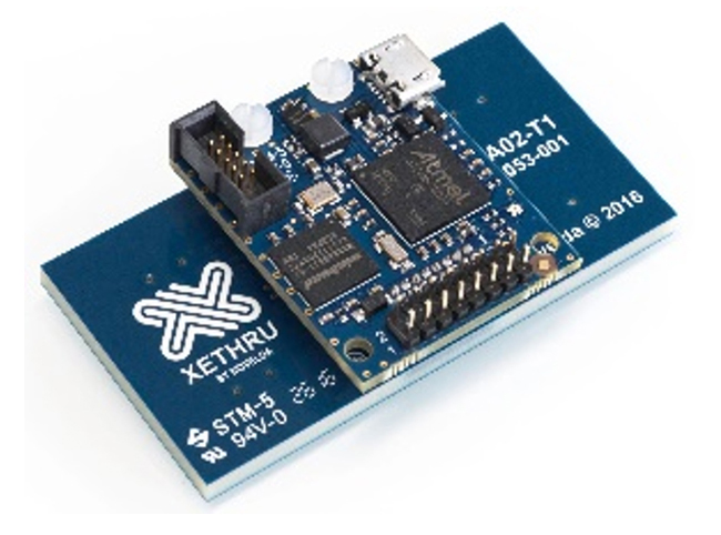
Figure 3 Novelda’s x4 UWB radar module.7
Link Analysis for HRP UWB Wireless Communication
Figure 4 shows the packet structure from IEEE 802.15.4z HRP UWB.2,5 The packet is divided into a synchronization header (SHR) that sets the reference time for ranging and synchronous demodulation and a data portion (DP) for transmitting data. Although it is one packet, the two portions use separate modulation methods.
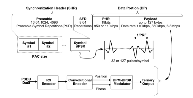
Figure 4 Packet structure from IEEE 802.15.4z HRP UWB.
The SHR is divided into a preamble and a start-of-frame-delimiter (SFD). The preamble is transmitted by repeating the same symbol, and its length is determined by the number of preamble symbol repetitions (PSR). One preamble symbol is defined by 31 or 127 sub-symbols, and each sub-symbol has a value of (-1, 0, 1). Here, ‘1’ means a UWB pulse with positive (+) polarity, ‘-1’ means a UWB pulse with negative (-) polarity and ‘0’ means no pulse. These pulses have a time interval that is the inverse of the PRF. The basic PRF (BPRF) mode of the IEEE 802.15.4z standard uses a PRF of 64 MHz. The SFD consists of eight or 64 symbols and indicates the end of the preamble and the start of the DP.
The preamble can obtain processing gain by repeatedly sending a known symbol without any special modulation. In HRP UWB, this is defined as the number of packet acquisition chunks (PAC). In addition to the processing gain by PAC, the preamble uses a leading-edge detection (LED) algorithm to increase ranging accuracy. That is, if the number of PSRs is 1024 and the PAC is 32, one channel impulse response (CIR) is generated by collecting preambles of 32 PACs and the LED algorithm is used to increase ranging accuracy by using 32 of these CIRs (=1024/32).1,8
The DP consists of a physical header (PHR) and a payload. The PHR contains information about the length and rate of the payload data and uses a different channel coding and modulation method than the SHR. Reed-Solomon (RS) coding and convolution coding are used for channel coding, and burst position modulation — binary phase shift keying (BPM-BPSK) modulation is used as a modulation method.
The reasons for using different modems for the SHR and data sections are as follows. Unlike the SHR, the DP does not send pulses repeatedly, so there is no processing gain. Instead, the coding gain through channel coding is used to balance the link between the preamble and the payload.
Because the ranging limit in HRP UWB communication is determined by the smaller link margin between the SHR link and the DP link, the parameters must be adjusted so that the two links are appropriately balanced. For HRP UWB to be successful, packets related to ranging must first be successfully exchanged. To do this, there must be no preamble errors or DP data errors; the link budget of the preamble and the link budget of the DP must be considered simultaneously.
DP Link Analysis
The link performance of the DP is determined by whether the packet reception is successful or not, and is usually given as a packet error rate (PER). In this article, a PER of 1 percent or more is set as the link performance criterion. This is a value commonly discussed in the current next-generation UWB standard, IEEE 802.15.4ab.9 The PER for BPM-BPSK used in UWB communication is generally determined by Equation (1).10
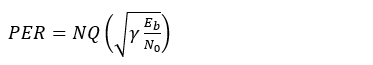
where N is the number of bits per packet, γ is the coding gain, Eb is the bit energy and N0 is the power density spectrum of noise.
Typically, UWB ranging requires ‘Poll,’ ‘Response’ and ‘Final’ packets, and the longest packet is the 24-byte ‘Final’ packet, so this packet should be used as the PER evaluation criterion.1 Since N is 192 bits, Eb/N0 of the DP is 9.0 dB, assuming 1 percent PER.
The IEEE 802.15.4z HRP UWB standard uses convolutional and RS channel coding, so it has a channel coding gain of about 5.6 dB.11 Therefore, the DP of the IEEE802.15.4z HRP UWB standard should have a Eb/N0 value of about 3.4 dB. Additionally, since the IEEE802.15.4z HRP UWB standard distributes one bit across multiple chips, the signal-to-noise ratio (SNR) is given by Equation (2).5
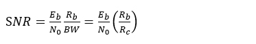
where BW is the bandwidth, Rb is the bit rate and Rc is the chip rate. According to the IEEE802.15.4z HRP UWB standard, when Rb is 850 kbps, the SNR is about – 24.3 dB and when Rb is 6.8 Mbps, the SNR is –15.3 dB. That is, when the data rate is as low as 850 kbps, the link margin becomes 9 dB, which can support a wider communication range than when it is 6.8 Mbps.
Next is the analysis of the DP link based on the SNR from Equation (2) and local regulations on UWB power in Table 1. The transmitted power is given by Equation (3).
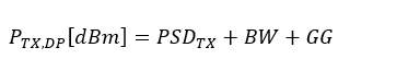
where PTX,DP is the transmitted power of the DP in dBm, PSDTX is the average power regulation of – 41.3 dBm/MHz, BW is the bandwidth in MHz and GG is the gating gain, respectively. The gating gain is given by Equation (4).
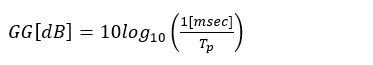
where Tp corresponds to the time length of the packet. It indicates that the power can be increased according to local regulations when the packet length is less than 1 msec. Typically, UWB IC manufacturers such as Qorvo and NXP provide the ability to control power through the gating gain when the packet length is shorter than 1 msec.6 Finally, receiver sensitivity is given by Equation (5).
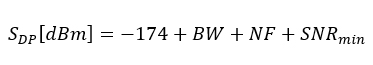
where, SNRmin is the minimum SNR, which is given by Equation (2), and NF is the receiver’s noise figure.