SHR Link Analysis
Next is the analysis of the ranging accuracy when data is successfully exchanged. In UWB communication, the ranging accuracy is related to the preamble and the root-mean-square (RMS) value of the ranging accuracy of the preamble is given by the Cramer-Rao bound (CRB). In general, the RMS of the ranging accuracy is given as a function of SNR and bandwidth as in Equation (6).8

Based on Equation (6), the ranging accuracy is expressed as a function of SNR and bandwidth (see Figure 5).
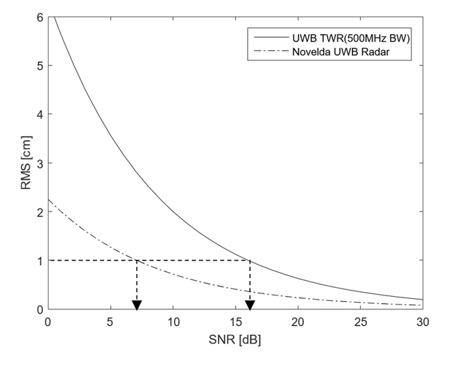
Figure 5 CRB for UWB ranging accuracy.
If the ranging accuracy is ±1 cm, the SNR of the UWB preamble requires 16 dB or more according to Equation (6). In other words, the preamble needs a 12.6 dB higher SNR value than the SNR value required by the DP in the UWB packet. The SNR value is increased by repeatedly transmitting the same symbol in the preamble. The processing gain is given by Equation (7).

where Np is the number of symbols used for ranging in the preamble. The number of symbols to be used for the processing gain of Equation (7) among the symbols in the preamble is defined by the PSR and PAC.
Using Equations (1) through (7), the link budget of the preamble link and the DP link for UWB communication can be determined. For example, a preamble link and a DP link with a data rate of 6.8 Mbps are shown in Figure 6.
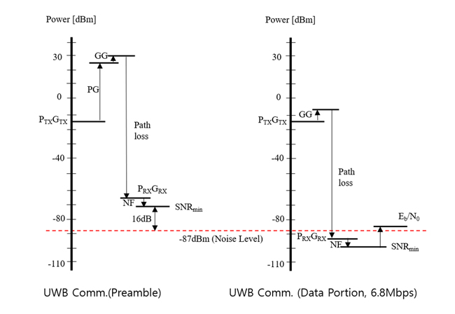
Figure 6 Link budget example for IEEE 802.15.4 HRP UWB.
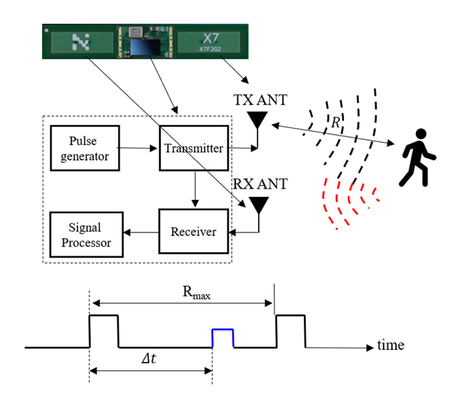
Figure 7 UWB radar.
LINK ANALYSIS OF HRP UWB RADAR
Figure 7 shows the UWB pulse radar operating principle. The transmitter up-converts a pulse train generated by the UWB pulse generator and sends it to the transmitting antenna (TX ANT), which radiates the UWB waveform. When this signal strikes an object at a certain distance, some of the signal is backscattered. The backscattered signal is received by a separate receiving antenna (RX ANT) and down-converted to baseband in the receiver. A signal processor calculates the time difference between the transmitted pulse and the received pulse. The distance to the target is given by Equation (8).

where c is the speed of the radio wave (the speed of light), and the number 2 is included because the radio wave travels a round-trip distance 2R. The link performance of the UWB radar is given by Equation (9).

Where σ corresponds to the radar cross section (RCS) of the object, and the transmitting and receiving antennas are typically located in front of the radar module and have a gain of several dBi. Unlike UWB communication, where PRX is inversely proportional to the square of the distance, for UWB radar, PRX is inversely proportional to the fourth power of the distance. The link budget determined by referring to the data sheet of Novelda's x4 UWB radar module is as shown in Figure 8.7
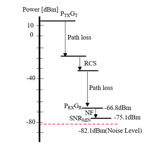
Figure 8 Novelda's x4 UWB radar module link budget.
Unlike UWB communication, UWB radar has no special coding gain or processing gain, so the link performance is poor, and the operating range is only within a few meters. When calculating the link budget of UWB radar, unlike UWB wireless communication, the link budget is based on peak power. Also, unlike UWB communication, UWB radar range depends on the RCS of the target. Assuming a sitting person as the target and assuming an RCS of 0.5 m2, the operating radius is theoretically calculated to be up to 2.9 m. In fact, the test results of Novelda's UWB radar have confirmed that it operates only within a narrow range of 1 to 2 m.6,7
Conclusion
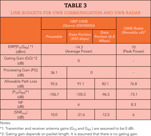
This article examines the characteristics of HRP UWB communication and UWB radar with a comparison and analysis of performance from the perspective of the link budget. The analysis results are summarized in Table 3 and Figure 9.12 UWB radar has the smallest operating range. It is theoretically up to 9.87 m, but it can detect changes in human movement within 2 meters.
Figure 9 Link budget comparison of different UWB technologies.
The operating range of a UWB communication link at a data rate of 850 kbps is more than twice as large as that at a data rate of 6.8 Mbps. The link performance of the preamble, which is the basis for synchronization and ranging, varies depending on its length. In the IEEE 802.15.4z HRP UWB standard, the length of the preamble varies from a minimum of 16 to a maximum of 4096 PSRs; a longer preamble has a larger operating range than a shorter preamble.
However, since a message must be successfully received for ranging, the characteristics of the preamble must be appropriately adjusted to the link of the DP. This is confirmed to be consistent with the results from many experimental papers.13,14
These results can be used for reference when it is necessary to revise local regulations in the future. For example, in Europe, the average output power spectral density of UWB was increased to -31.3 dBm/MHz to activate UWB services. In addition, the results of this study can help to adjust physical layer parameters when installing UWB communications and UWB radar products to increase the operating range.
References
- B. J. Jang, “Principle and Trends of UWB Positioning Technology,” Journal of the Korean Institute of Electromagnetic Engineering and Science, Vol. 33, No. 1, January 2022, pp. 1-11.
- P. Sedlacek, M. Slanina and P. Masek, “An Overview of the IEEE 802.15.4z Standard its Comparison and to the Existing UWB Standards,” 29th International Conference Radioelektronika, April 2019.
- C. J. Kim, B. Han, J Lee, S. W. Jung and B. J. Jang, “Sensor Application Using UWB Communication: In-Vehicle Seat Occupancy Detection,” Journal of the Korean Institute of Electromagnetic Engineering and Science, Vol. 34, No. 4, April 2023, pp.249-255.
- S. Ahmed and S. H. Cho, “Hand Gesture Recognition Using an IR-UWB Radar with an Inception Module-Based Classifier,” Sensors, Vol. 20, No. 2, January 2020.
- IEEE 802.15.4z-2020—IEEE Standard for Low-Rate Wireless Networks — Amendment 1: Enhanced Ultra-Wideband (UWB) Physical Layers (PHYs) and Associated Ranging Techniques, IEEE Standards Association, August 2020.
- DW3000 User Manual, Decawave, May 2021.
- Ultra-Low Power Presence Sensor, Novelda. Web: https://novelda.com/ultra-low-power-sensor/.
- I. Domuta, T. P. Palade, E. Puschita and A. Pastrav, “Timestamp Estimation in P802. 15.4 z Amendment,” Sensors, Vol. 20, No. 18, September 2020.
- A. R. Kabbinale, A. Bansal and K. S. Gopalan, “Towards Next-Generation Ultra-Wideband Technology,” 15th International Conference on Communication Systems & Networks, January 2023.
- J. G. Proakis, Digital Communications, McGraw-Hill, 2020.
- A. F. Molisch, D. Cassioli, C. C. Chong, S. Emami, A. Fort, B. Kannan and M. Z. Win, “A Comprehensive Standardized Model for Ultrawideband Propagation Channels, IEEE Transactions on Antennas and Propagation, Vol. 54, No. 11, November 2006, pp. 3151-3166.
- S. Han and B. -J. Jang, “Extending the Coverage of IEEE 802.15.4z HRP UWB Ranging," Sensors, Vol. 25, No. 10, May 2025.
- M. Stocker, H. Brunner, M. Schuh, C. A. Boano and K. Römer, “On the Performance of IEEE 802.15.4z-Compliant Ultra-Wideband Devices,” Workshop on Benchmarking Cyber-Physical Systems and Internet of Things, May 2022.
- B. Großwindhager, C. A. Boano, M. Rath and K. Römer, “Enabling Runtime Adaptation of Physical Layer Settings for Dependable UWB Communications,” IEEE 19th International Symposium on ‘A World of Wireless, Mobile and Multimedia Networks,” June 2018.