
A horn antenna uses a metamaterial (MTM) located between the coaxial feed and the horn that is the foundation for dual-band operation and filtering. Simulation and measurement demonstrate good impedance matches around 3 and 4.35 GHz owing to the coupling in the coaxial feed and probe coupling in the horn. Gain on boresight is approximately 6.6 dB at 3 GHz and 9.5 dB at 4.35 GHz. Furthermore, out-of-band gain suppression is approximately 29 and 32 dB, relative to the maximum gains in the two passbands.
Horn antennas are extensively employed in communication systems owing to their wide bandwidths, good radiation patterns and simple structures.1-3 They serve as standard gain antennas for system testing,4,5 provide reliable feeds for antenna arrays6-8 and can be configured as horn antenna arrays as well.9,10
Numerous attempts have been made to improve their performance, such as enhancing integration, improving gain, incorporating a filtering response and providing dual-band operation. For example, planar horn antennas, based on a printed circuit boards, groove gap waveguide or substrate-integrated waveguide have been developed for improved system integration.11-13 Lenses or MTMs have been used to enhance gain.14,15 A filtering response can be achieved by embedding split ring resonators (SRRs) or via-hole arrays.16-18 Dual-band horn antennas can be constructed by using two helix exciters or combining them with tapered slot antennas.19,20 Furthermore, stepped horn antennas can be integrated with two different filters to achieve a dual-band filtering response.21
In this work, an MTM consisting of a square waveguide (WG) with centrally loaded complementary electric SRRs (CeSRRs)22 is used to construct a dual-band filtering horn antenna without additional filters.
MTM HORN ANTENNA CONFIGURATION
The antenna includes a coaxial feed, an MTM with six-unit cells, a WR-284 rectangular waveguide and a horn aperture (see Figure 1). The MTM unit cell, which comprises a square waveguide and CeSRR, has two operating modes and is the foundation for dual-band operation and filtering. A coaxial feed ensures a good impedance match between the standard SMA connector and the MTM, which is derived from the coaxial coupler of the MTM-inspired backward wave oscillator of Tang et al.23
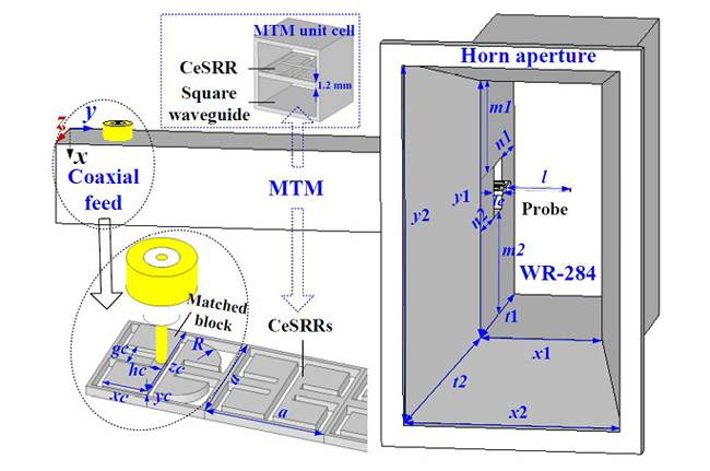
Figure 1 Dual-Band filtering horn antenna configuration.
The part of the CeSRR with the cylindrical probe is inserted into the WR-284 rectangular waveguide for transformation from the TM mode of the coaxial feed to the TE mode in the WR-284 rectangular waveguide. The WR-284 rectangular waveguide, with one short end and the other end connecting to the horn aperture, serves as a bridge to connect the MTM to free space. The MTM horn antenna is optimized using CST Microwave Studio24 and the corresponding parameters are listed in Table 1. The detailed parameters of the CeSRR can be found in the work of Duan et al.22
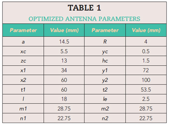
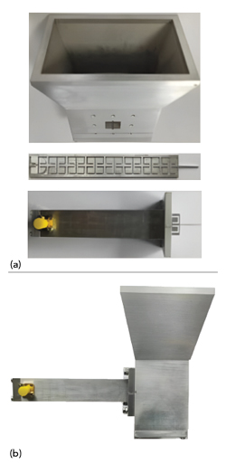
Figure 2 (a) Fabricated components and (b) assembled prototype antenna.
RESULTS AND ANALYSIS
Reflection Measurements
The aluminum MTM horn antenna prototype is shown in Figure 2. Low speed wire electrical discharge machining with a 0.005 mm fabrication tolerance is employed to fabricate the CeSRRs with the matched block.
Simulated and measured |S11| obtained using CST Microwave Studio24 and a vector network analyzer, respectively, exhibit good agreement and show that the antenna has two passbands centered at approximately 3 and 4.35 GHz (see Figure 3). Slight discrepancies are attributed to fabrication tolerances of the CeSRRs.
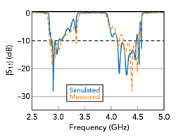
Figure 3 Simulated and measured |S11|.
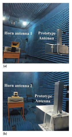
Figure 4 Radiation pattern measurement setup: (a) first passband and (b) second passband.
Far Field Radiation Characteristics
Measurement of the prototype antenna’s far field radiation characteristics in a microwave anechoic chamber is shown in Figure 4. Two test antennas are used; one is a 15 dB standard gain horn operating from 2.6 to 3.95 GHz, and the other is a 10 dB standard gain horn operating from 3.9 to 6 GHz.
Simulated compared with measured gain is shown in Figure 5. Measured results indicate that the MTM horn antenna has a maximum realized gain of approximately 6.5 dBi in the first passband around 3 GHz and approximately 9.5 dBi in the second passband around 4.35 GHz. In comparison, the gain in the stopband drops sharply to approximately -22.5 dB, indicating an out-of-band gain suppression level (OBGSL) of approximately 29 and 32 dB with respect to the maximum realized gains in the first and second passbands, respectively.
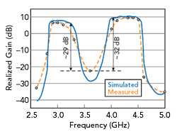
Figure 5 Simulated and measured gain.
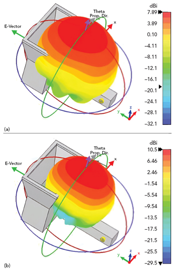
Figure 6 Simulated 3D radiation patterns at (a) 3 and (b) 4.35 GHz.
Simulated 3D far field radiation patterns are shown in Figure 6, and simulated radiation patterns are compared with measured patterns at 3 and 4.35 GHz in the xoz and yoz planes (see Figures 7 and 8), respectively. Measured results agree well with the simulation. On boresight, the x-pol is 20 dB lower than the co-pol.
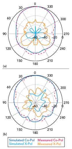
Figure 7 Simulated and measured normalized radiation patterns at 3 GHz: (a) xoz plane and (b) yoz plane.