
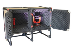
Figure 1 mmWave and sub-THz antenna test setup.
Antenna test setups play a critical role in the design and optimization of wireless systems. When designing an antenna, the engineer typically starts by using electromagnetic (EM) software simulators to optimize the antenna’s specifications for parameters such as gain, efficiency, bandwidth, beamwidth and polarization. Once the antenna is manufactured, it must be tested over-the-air (OTA) to validate that the fabricated antenna performance matches its specifications.
An antenna test setup for OTA qualification is composed of an anechoic chamber, an antenna positioner and a probe attached to an instrument with software recording the measurements, as shown in Figure 1.
THE BOTTLENECK FOR MMWAVE ANTENNA TESTING
mmWave technology was traditionally defined to cover the radio frequencies from 30 to 300 GHz. At these mmWave and sub-THz frequencies, the short wavelengths have several implications.
First, the signal routing from the MMIC to the antenna with length > λ/10 cannot be neglected or treated as a lumped component. At lower frequencies, the antenna can be measured in isolation from the rest of the RF chain at the port. However, at mmWave, the MMIC and antennas cannot be accurately measured independently, and any testing will require a radiated OTA test measurement.
Secondly, to overcome path loss, phased array antennas are commonly used at mmWave frequencies to increase gain and directivity. These can be fixed passive arrays, but usually are active beamforming phased arrays with dynamic phase shifters to steer the radiating energy. In the latter case, the antenna is no longer a simple device, and the radiation pattern of the antenna array cannot be isolated from the rest of the system.
When large engineering teams work on such complex wireless systems, nearly every single design iteration can directly impact the gain, radiation pattern and directivity. If the team has one traditional chamber to share or go offsite to test, the design progress grinds to a halt.
SOLVING THE BOTTLENECK AT MMWAVE AND SUB-THZ
Antenna performance is typically characterized in the far field. The far-field distance (d) is the boundary after which the wave patterns become relatively uniform with fields that fall off in amplitude by 1/r. The far-field distance can be calculated using Equation 1, where D is the diameter of the antenna and λ is the wavelength.
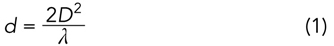
For example, if engineers have a 4 × 4 antenna array with antennas spaced λ/2 apart, the far-field boundary can be calculated as d = 9λ, since D is the distance between the farthest elements of the array. At 28 GHz, this yields a far-field boundary of 9.6 cm. In the sub-THz range, this distance is even shorter.
Consequently, a small benchtop mmWave chamber on a lab bench is adequate for most antenna arrays. With multiple team members having access to their own antenna test setup, the iterative effort becomes easier. Sharing one resource cannot compete with a multitude of small team-allocated antenna test benches. This is when getting small, affordable OTA antenna test setups for mmWave and sub-THz performance is the solution.
COMPACT MMWAVE AND SUB-THZ ANECHOIC CHAMBERS
Because the wavelength at mmWave is small, the far-field distance is generally reduced when the array size stays small. With this, the overall dimension of the system can be adjusted to something 1 to 2 meters in length and remain in the far field. The compact chambers are portable, more convenient and lower cost than traditional microwave chambers.
The isolation strategy also changes when considering requirements for higher frequencies, such as mmWave and sub-THz. Lower frequencies have a longer range and penetrate obstacles more easily, causing interference. In contrast, for mmWave and sub-THz frequencies, outside interference is minimal. For one, the propagation at those frequencies is low. In addition, the spectrum is very wide, lowering the chance of accidental interference. Furthermore, because higher frequencies need a higher gain directional antenna to propagate further, the chance for internal stray reflection increases significantly. In other words, in microwave frequencies, the chance for outside interference is high and internal reflection is low, whereas in mmWave and sub-THz frequencies, the opposite is true — the chance of outside interference is low, but internal stray reflection is much higher. Therefore, MilliBox uses non-metal enclosures since they reduce internal reflections and introduce a minimal risk of outside interference.
AUTOMATED POSITIONER FOR RADIATION PATTERN MEASUREMENTS
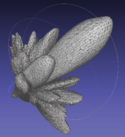
Figure 2 Radiation pattern from a 28 GHz 8 x 8 phased array system.
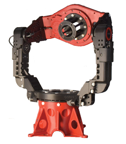
Figure 3 mmWave 3-axis antenna positioner.
When the antenna under test is placed on a positioner, the transmitted power can be measured from a distant point where a probe or a feed horn is placed. As the antenna is rotated, additional points are captured, creating a clear graph of the power level at different angles, constituting a radiation pattern.
Radiation patterns verify that the antenna is propagating its power in the desired direction. Elaborate antennas, such as horns and phased arrays, are directional and intended to transmit power in a specific direction. A 3D positioner becomes indispensable for these measurements.
3D antenna positioners have two or more rotation axes with motors controlled by software. This controls the antenna position on one side and connects to an instrument on the other end, allowing it to plot a 3D image of the radiation pattern directly. A typical 3D radiation pattern from a phased array is shown in Figure 2.
CHARACTERISTICS OF An MMWAVE ANTENNA POSITIONER
Generally, a positioner is defined by its size and weight capacity, its number of rotation axes and its angular resolution. Figure 3 shows a MilliBox 3-axis antenna positioner. MilliBox aims to reduce the risk of stray reflection, so they manufacture the body of the positioner with non-metal materials. Positioner bodies can be made of organic material, such as plastic or foam, or covered in absorbing material.
Capturing OTA data can be done in many ways; therefore, the flexibility of having the positioner’s controller in source code is a great advantage. Python, a free and well-known program, is the first choice to control the positioners. Additionally, having the data capture output in a portable format, such as CSV, helps broaden the choice of data visualization tools.
Wiring and signal routing are often afterthoughts that can have disastrous consequences. Having all rotation axes hollowed such that the cables can be routed through reduces cable length and torsion stress on those cables. For instance, low-profile cable assemblies are compatible with automated 3D antenna positioners, and when waveguide is the only practical device under test connectivity, embedding frequency extenders into the 3D positioners is a solution.
OPTIMIZED ANTENNA TEST SOLUTIONS
The needs for antenna test solutions at mmWave frequencies and beyond differ from those of lower frequency microwave testing, and having multiple test setups available to design engineers increases throughput and efficiency. MilliBox offers a line of anechoic chambers and antenna positioners that cater to the specific requirements of the mmWave and sub-THz wireless markets.