
In addition to test instrumentation, such as a vector network analyzer (VNA), the test fixture for the device under test (DUT) is a critical element of RF benchtop evaluation. The DUT can range in complexity from a single chip or component to an entire printed circuit board (PCB) subsystem. When assessing the performance of a DUT, the ideal scenario is to have the test equipment directly connected to the ports of the DUT. However, this approach is typically not feasible due to practical considerations. Therefore, a test fixture is used between the DUT and the test equipment.
The test fixture usually consists of a combination of connectors, cables and PCBs. One of the main goals for the test fixture is to make it as electrically transparent as possible. This means the fixture should not affect the measurement results across the full bandwidth of the measurement being made. Further analysis on de-embedding test fixtures and considerations is given by S. Sankararaman et al.1
This article reviews how some types of interconnects (cables and connectors) in benchtop RF tests have evolved in response to changing test needs in the context of the important technical challenges for modern test fixtures.
TECHNICAL CHALLENGES
VNAs are commonly used in RF benchtop tests. These powerful and versatile tools have evolved dramatically since the introduction of commercially available VNAs in the 1970s. At that time, these devices were made up of multiple bays of test racks of various instruments. Since their inception, VNAs have developed into systems with fast sampling rates, FFT-based spectrum analysis, wide bandwidths and deep memory to support the analysis of complex wideband signals. The relatively recent addition of a direct digital synthesis allows newer VNAs to expand from narrowband analysis to nearly unlimited bandwidth possibilities.2
Fortunately, the technological advances in VNAs have also dramatically increased the speed of measurements. For example, full-band frequency sweeps in the 1970s could easily take more than one hour. Today, VNAs can complete a frequency sweep in a fraction of a second. This speed change enhanced the role of the VNA and enabled real-time measurement capability, often incorporating environmental stimuli such as temperature changes and vibration. It is important to note that these stimuli not only affect the performance of the DUT, but also the test fixturing.
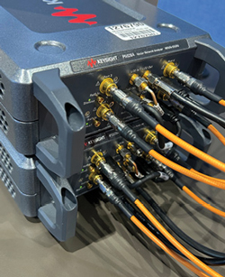
Figure 1 Samtec Nitrowave™ cables in a test application using Keysight P502A USB VNAs.
As microwave devices and systems continue to proliferate, new frequency bands, such as 32 GHz and 43.5 GHz, become important for applications like 5G wireless and K-Band satellite communications. The VNA cables that support benchtop RF testing are commonly optimized for minimal loss and phase stability over time, flexure and temperature. An example of a VNA and its associated cables is shown in Figure 1. With applications in new bands, there are opportunities to optimize new cable and/or connector variants. For example, a cable design optimized for 32 GHz can provide a lower loss solution than a cable that was optimized for 40 GHz.
In addition, today’s test fixtures require interconnects, both cables and connectors, to support higher physical channel counts than ever before and provide higher density in a reduced space. They must operate with high linearity, meaning no suckouts or non-linear phase changes in the band and demonstrate repeatability after mating/unmating the interconnects. This is especially true in the initial system bring-up. Satisfying all these interconnect needs in cables and connectors has been challenging for interconnect suppliers.
CABLE AND CONNECTOR EVOLUTION
In the early days of RF benchtop testing, choosing a cable or connector was often an afterthought. Designers frequently used whatever was available. Today, connecting to the PCB can be accomplished with a variety of different interconnects, each with its advantages and disadvantages for handling complex signals.
SMA Connectors
Since the 1960s, sub-miniature version A (SMA) connectors have served RF and microwave applications. Today, they are used in applications up to 27 GHz. Traditionally, SMAs were soldered onto the board using through-hole technology. Later, surface-mount versions became popular and edge-mount SMAs were used for the highest frequency applications. Older connectors, especially through-hole designs, are well suited for use in rugged conditions that see heavy use. However, these connectors may require extensive skill and/or expensive tooling to get optimal results. SMA connectors can still be an excellent choice due to their wide availability and notable ruggedness as long as their bandwidth supports the DUT’s upper-frequency limit.
Compression-Mount Connectors
Existing in some form or another since the 1960s, compression RF connectors have gained favor recently since they can more readily support higher frequencies. This has a lot to do with the solder joints, more specifically, eliminating them. At lower frequencies, solder joints have proven to be a reliable method of attaching interconnects. However, as frequencies and data rates have increased, the inevitable variations in attributes like the size and shape of solder joints translate into variations in electrical performance.3 With solderless connectors, the electrical contact is established between the two contacts by screwing the connector to the PCB. Over the years, push-on compression-mount connectors have been adapted to use threads to provide more consistent performance and ensure secure attachment.

Figure 2 Samtec REF-228591 evaluation kit with multiple compression-mount connectors.
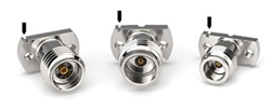
Figure 3 Alignment features indicated with arrows.
Compression-mount connectors provide several advantages. These include improved signal integrity compared to soldered connectors, faster assembly and the ability to remove and reuse, which can be very helpful in a test fixture for RF benchtop testing.4 For instance, Samtec test fixture cards are optimized for breakout performance, allowing users to swap out their compression-mount connectors quickly, depending on the test setup. Figure 2 shows an example of the Samtec REF-228591 evaluation kit containing 1.35 mm, 1.85 mm, 2.40 mm and 2.92 mm compression-mount connectors.
Unlike soldered connectors, compression-mount connectors access the PCB signal layers through micro-vias. This avoids the need for large through-holes and blind vias. In terms of performance, this can translate into excellent impedance, which improves high speed transmission.4
THE IMPORTANCE OF ALIGNMENT
Small compression-mount connectors are well suited for use in test, prototype and diagnostic applications. This is due, in large part, to their performance and ease-of-use advantages. One concern with these types of connectors is the risk of misalignment. Unfortunately, it can be challenging to detect this misalignment.5,6
Interconnects are needed at all signal inputs and outputs. At higher frequencies, even slight misalignments of a connector are sufficient to cause failure.7 Fortunately, the industry has addressed connector misalignment by adding visual indicators to aid in the proper alignment of small compression-mount connectors, as shown in Figure 3. These alignment marks can significantly speed up assembly and alignment while improving yield. These alignment features work with fiducials on the PCB to ensure proper placement and contact of the compression-mount connectors. Ganged connectors are also available with alignment features to help avoid misalignment.
GANGED SOLDERLESS INTERCONNECTS
As the need for connectors in a test fixture increases, the design can become bulky and space-constrained. A solution to this challenge has been the regular use of ganged solderless connectors in RF benchtop testing. A ganged connector enables more channels. In addition, ganged solderless compression systems can improve the speed of swapping out connectors, reliability and real estate issues.
Figure 4 shows an example of a Samtec Bulls Eye® high performance test assembly with ganged solderless connectors and cables. Our research shows that a configuration like the one shown in Figure 4 can have good performance because cable losses are lower than PCB losses. Further minimizing loss, ganged connectors increase connection density and they can be placed closer to the DUT.
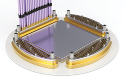
Figure 4 A ganged compression connector simplifies test fixture board design.
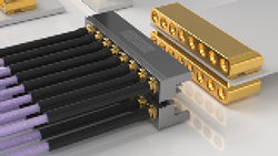
Figure 5 Belly-to-belly ganged connector configuration.
The benefits of ganged connector solutions can be leveraged even more by changing the plane in which the cables approach the fixture. This becomes particularly important when the test fixture has z-height restrictions. In these applications, bringing the cables in parallel to the PCB is advantageous. There can also be density improvements from unique solutions that enable connectors to be mated on both sides of the PCB, also known as “belly-to-belly,” as shown in Figure 5 for Samtec’s Magnum RF® GPPC-RA-SM product with a 3.94 mm (.155 in.) profile.
PERFORMANCE ANALYSIS
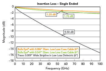
Figure 6 Insertion loss comparison for ganged cable connectors and a stripline trace.

Figure 7 Phase stability before and after 500,000 cycles of flexure.
To demonstrate the advantages of the ganged connector configuration, two ganged cable connectors and a circuit trace of the same length are analyzed. The goal of this analysis was to understand the insertion loss (IL) and return loss performance for a test fixture over a wide frequency range. Figure 6 shows a comparison of loss for a circuit trace and two ganged cable connectors. One of the ganged connectors uses 0.047 in. diameter low loss cables and the other uses 0.086 in. diameter low loss cables. The results indicate that ganged cable connectors minimize fixture IL substantially, especially as frequency increases, when compared to a low loss dielectric stripline trace of the same 6 in. length as the cables. These results give test fixture designers confidence when using ganged compression-mount connectors.
When using a VNA, interconnect phase and amplitude stability are key considerations for optimal performance. For cables in particular, stability over flexure is critically important, as different test points are accessed on the fixture. For consistent measurements, switching to a low loss, high performance microwave cable works very well in dynamic applications. Figure 7 shows cable return loss performance to 50 GHz for a Samtec Nitrowave LL043 Series cable before and after 500,000 flexure cycles. In this case, the cable, which is well suited for use in RF benchtop testing applications, incorporates an interlayer in its construction. This architecture is a major contributor to the overall performance stability.
IMPORTANCE OF CABLES
The cables used in the analysis are high performance microwave cables. As the connectors described in this article have evolved in RF benchtop testing, the associated cables have also evolved. Standard microwave cable types, like the RG142 50 Ω cable, are available from many different suppliers. Additionally, VNA suppliers, such as Rohde & Schwarz, also supply cables for test applications.8
Some designs require high performance, multi-channel cables and there is also a growing need for flexible cables for benchtop testing and other applications. Products like the W. L. Gore & Associates PHASEFLEX® Microwave/RF Test Assemblies9 and Samtec’s Nitrowave cables10 provide excellent mechanical durability and electrical performance over flexure. This is important because when a test fixture is calibrated, the cable is typically in one static position. However, after calibration, the cable may be moved to different test points on the device. In this case, stability becomes important to maintain a calibrated signal.
LOOKING AHEAD
Throughout the evolution of RF benchtop testing, interconnect suppliers and instrumentation vendors have made their products easier to use. This evolution has provided more consistent performance and supported expanding frequency ranges. Interconnect suppliers are expected to continue adapting to the changes made by test equipment manufacturers. The need for greater channel counts and higher density will continue to drive the need for ganged connector solutions at lower pitch and higher bandwidth.
Additionally, the opportunity to upgrade existing technology will become increasingly important. An example of this is 1 mm connectors, which have traditionally been rated to a maximum frequency of 110 GHz. New applications have spurred the need to upgrade designs and push these connectors and cables to operate at 125 GHz or even higher frequencies. Undoubtedly, times have changed and great attention is now being placed on interconnect technology. As new technological challenges emerge, manufacturers will continue to advance the state-of-the-art in interconnects.
References
- S. Sankararaman, S. Tucker, I. Novak and G. Blando, “Realistic Use Cases for Edge, Angled, and Vertical Launch Connectors up to 100GHz,” DesignCon 2024.
- J. P. Dunsmore and J. -P. Teyssier, “The Evolution of Vector Network Analyzers to Provide Precision Vector Spectrum Analysis for 6G Applications: VNA Evolves for 6G EVM Signals,” IEEE Microwave Magazine, Vol. 25, No. 12, Dec. 2024, pp. 77–90, doi: 10.1109/MMM.2024.3438711.
- “Webinar: Impact of Solder Reflow on High Bandwidth Connectors, Samtec gEEk® spEEk,” Samtec, Web: https://www.samtec.com/support/videos/webinar-impacts-of-solder-reflow-on-high-bandwidth-rf-connectors-781934976/.
- “What are Solderless Compression Mount Connectors?,” everything RF, https://www.everythingrf.com/community/what-are-solderless-compression-mount-connectors.
- “Mechanical Consideration for Compression Mount RF Connectors,” Samtec gEEk® spEEk, December 2022.
- Jean-Jacque DeLisle, “How to Reliably Align Compression Connectors for Millimeter Wave Applications,” Microwave Journal, Vol. 66, No. 3, March 2023, pp. 70-80.
- M. Griesi, Z. Speraw, E. Loy and S. Wronowski, “Millimeter Wave Design: Optimizing Performance in RF Compression Mount Connectors,” Samtec, Web: https://suddendocs.samtec.com/notesandwhitepapers/samtec-millimeter-wave-design.pdf.
- VNA accessories, Rohde & Schwarz.
- “Data Sheet: GORE® PHASEFLEX® Microwave/RF Test Assemblies,” Gore.
- High-Performance RF Microwave Cable Assemblies, Samtec, Web: https://www.samtec.com/rf/cables/high-performance-microwave/.