

Software-defined radios (SDRs) enable an increasing number of mission-critical systems across radar, electronic warfare, signals intelligence, communications and other defense applications. The essential requirements of these systems are performance, reliability and price. SDRs are typically designed to include an analog RF front-end (RFE), digital-to-analog converters (DACs) for the transmit path, analog-to-digital converters (ADCs) for the receive path and a digital processor. This article focuses on the analog RFE. It compares the three most common architectures with a deep dive into the architecture that is typically the best approach for mission-critical applications.
ARCHITECTURES
Various RF architectures can be utilized in SDRs, but the most prevalent are direct sampling, direct conversion (zero-IF) and superheterodyne.
Direct Sampling Architecture
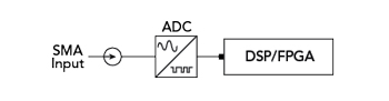
Figure 1 Direct sampling architecture block diagram.
Direct sampling, or direct RF sampling, involves digitizing the RF signal directly using an ADC without any prior frequency conversion. A representative block diagram of this architecture is shown in Figure 1. This approach is simple in design and offers wideband operation, limited only by the ADC. While this design enables simultaneous processing of a wide range of frequencies, this architecture usually sacrifices RF performance, especially dynamic range, which is essential in many mission-critical applications. This issue is further complicated by high power consumption and the prices of the high speed converters required for these architectures.
Direct Conversion (Zero-IF) Architecture
Another architecture to consider is direct conversion or zero-IF. In this architecture, the signal is down-converted directly to a DC baseband signal in one step using mixers. A representative block diagram of this architecture is shown in Figure 2. Although slightly more complicated than the direct sampling architecture, this approach simplifies the filter design since it requires only lowpass filters as needed. The RF performance is mid-range in this architecture as it offers efficient spectrum usage because the absence of intermediate frequencies reduces the risk of images. Despite reducing image signals, this architecture does introduce DC offsets and I/Q imbalances that can cause distortion. This architecture is also susceptible to low frequency noise, so it is classified as having mid-range RF performance.

Figure 2 Direct conversion architecture block diagram.
Superheterodyne Architecture
The superheterodyne architecture is more complex. This approach involves converting the RF signal to an intermediate frequency (IF) before digitization and while this is a well-established RF architecture, it can be challenging to implement. The representative block diagram for this architecture is shown in Figure 3. SDRs that implement this design provide the benefits of high selectivity, sensitivity and dynamic range. By offering excellent filtering characteristics and the ability to amplify only the desired signals, these SDRs provide superior performance when operating in congested or contested RF environments. With the ability to handle a broad range of signal strengths effectively, SDRs with this superheterodyne architecture become the clear choice for many mission-critical applications.
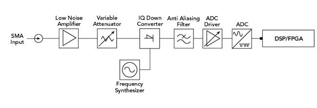
Figure 3 Superheterodyne architecture block diagram.
These systems have some drawbacks, but many are abstracted from the end user and the burden falls to the RF designer and SDR manufacturer. The design of this architecture adds stages within the RF chain and more components are often needed to achieve optimal performance. This means these designs are usually complex and can increase the overall size and cost of the SDR. There is also the possibility of image frequency interference being present, which is often addressed through added filtering and image-rejection mixers. This can lead to higher power consumption and costs.
COMPONENT SELECTION FOR THE SUPERHETERODYNE ARCHITECTURE
The rest of this article focuses on the components included in most superheterodyne architectures and the essential characteristics associated with component selection. The superheterodyne architecture is an excellent choice for mission-critical systems. Its structure includes several stages. Each stage requires specific components, which are discussed in the following section. The critical characteristics to consider when selecting these components are highlighted.
The first stage of the superheterodyne architecture has the RF connector, filter and low noise amplifier (LNA). The RF connector selection may appear trivial, but there are important elements to consider for the first component within the architecture. It is essential to consider the following:
Frequency Range: The connector must be rated for the system’s frequency range. Otherwise, the RF performance may be degraded immediately as signal integrity issues and losses can occur if the connector is not rated to the correct frequency range.
Insertion Loss: High insertion loss can reduce receiver sensitivity and lead to poor performance. Low insertion loss connectors are essential to ensure the best overall performance.
Power Handling Capacity: The connector must work at the maximum specified system power. Exceeding the connector’s power handling capacity can result in signal integrity issues, failed connections and overheating.
Price and Availability: It is critical to ensure that the connector selection supports the production schedule and that the price does not negatively impact the overall system price for the target applications.
The RF filter is the next element to consider in the design. The filter removes out-of-band signals to prevent them from reaching the later stages. These filters can be designed from discrete components or as an integrated chip to meet the performance and design requirements. The key parameters that must be evaluated when selecting the proper RF filter are bandwidth and selectivity. The filter must work at the maximum signal power without distortion while offering aggressive filtering to ensure unwanted signals are effectively removed before entering the remaining sections of the radio chain.
The last element within the first RF stage is typically the LNA. The LNA amplifies weak signals while limiting the noise added to the incoming signal. LNAs are designed for better overall RF performance, unlike traditional amplifiers that can produce extra noise. The key characteristics to consider for this component are noise figure, gain and linearity. The noise figure refers to the amount of added noise from the amplifier. The gain of the amplifier relates to how much the weak signals will be increased, ideally without added distortion. Linearity is critical to minimize intermodulation distortion, which can degrade signal quality.
The next stage in the superheterodyne architecture contains the system’s mixing elements, which change the signal frequency. These elements are the mixer and local oscillator (LO). A mixer is a nonlinear three-terminal device. The LO signal drives the mixer diodes and the mixer produces output frequency signals based on the sum and difference of the RF and LO signal frequencies. If the incoming RF signal is being down-converted, the intermediate frequency (IF) from the mixer will be the difference between the RF and LO frequencies. When selecting the appropriate mixer within a system, looking for high conversion gain, low noise figure and good isolation between ports is important.
High conversion gain is an important feature. It contributes to a better signal-to-noise ratio (SNR), reducing the need for more amplification within the system. It also increases sensitivity and improves the receiver’s ability to detect weaker signals. This improves the overall dynamic range of the system, enabling a wider range of signal strengths without exceeding allowable distortion levels, which enhances performance in weak signal conditions.
Good isolation between ports is also an essential selection criterion for the mixer. High port-to-port isolation helps to minimize signal and LO leakage, avoid IF feedthrough, reduce intermodulation products and improve receiver sensitivity and dynamic range. Because the superheterodyne architecture relies heavily on this set of characteristics for good performance, mixer selection is crucial.
As mentioned, the mixer relies on the LO signal to drive the nonlinear mixing elements to the proper levels and at the right frequency. The LO generates a stable frequency signal with a value selected to mix with the RF signal and produce the proper IF frequency. LO choice is also critical for the superheterodyne architecture and the key characteristics to evaluate include frequency stability, phase noise and tuning range. A stable LO ensures a consistent conversion frequency, while the low phase noise minimizes signal degradation. The wide tuning range is important as it allows the flexibility to generate different IFs for various applications, which is the key element for wideband operation.
Next in line is the IF stage. This section contains the IF filter and IF amplifiers. An IF filter is designed to pass the desired IF signal and reject others. This provides the selectivity that enables better performance. The key specifications of the IF filter are center frequency, bandwidth and shape factor. A narrow bandwidth improves selectivity, while a good shape factor ensures efficient signal separation with minimal adjacent channel interference. The filter should also have low insertion loss to preserve signal strength and low SNR for better sensitivity.
The IF amplifier, as the name suggests, amplifies the filtered IF signal to a level suitable for demodulation. The key parameters for this component are gain, bandwidth and linearity. The gain and bandwidth are important to ensure that the IF signal has the appropriate signal strength to drive the demodulator across the entire signal bandwidth. Linearity is an important parameter because it affects signal integrity and distortion before it reaches the demodulation stage. Other parameters influencing the optimal IF amplifier selection are noise and dynamic range. The noise added to the signal should be low and the dynamic range should be high to ensure varying signal strengths do not create distortion.
The demodulator is the fourth stage. This single component is vital as it extracts the original information from the modulated IF signal. The critical selection criteria for this stage relate to the demodulator type or modulation scheme and signal processing capability. Performance metrics include sensitivity, selectivity and noise immunity. The demodulator should accurately recover the signal with minimal distortion and offer the necessary signal processing capabilities based on the application. Ensuring compatibility with the modulation type and sufficient processing power for real-time signal processing is essential. Other available features in the advanced demodulator selection process include error correction and signal enhancement features.
The final stage is baseband processing. The components for this stage are the ADC and digital signal processor (DSP). The ADC converts the analog demodulated signal to a digital format. Several processes occur within this chip and there are many different characteristics to consider, with some directly impacting the platform’s utility for specific applications. The four key elements are the number of channels, resolution (number of bits), sampling rate and dynamic range. The number of channels relates to the number of RFEs the DSP must support and the architecture being implemented. The resolution is another key element, as higher resolution can help improve signal fidelity, SNR and overall data quality. For example, in test and measurement applications, the number of bits directly correlates to the accuracy and measurement reliability. In this case, higher resolution is better. The sampling rate directly limits the receiver’s bandwidth and affects signal fidelity. It can also help reduce aliasing, which will occur when the sample rate is too low and may cause a false lower frequency signal component to appear in the sampled data. The sampling rate will directly contribute to post-processing flexibility. The power consumption of the ADC is always an important consideration to ensure it operates properly within the intended system performance and environmental constraints.
The DSP stage can come in many forms. It can be a field programmable gate array (FPGA) or another dedicated DSP chip. Regardless of the component choice, the digital signal is processed for further operations like decoding, filtering and error correction at this stage. The processing speed, amount of logic resources, programmability and power consumption are critical considerations for this element. It is important to consider how much data will be processed and, if application-specific, what specific DSP operations are required. For greater flexibility, ensuring that the chipset is fast with a large number of logic resources will enable real-time processing and advanced operations. The programmability of the DSP directly influences the flexibility to change functionality along with allowing updates and modifications that are often necessary to adapt to different signal types and conditions.
In many instances and for many applications, it is beneficial for the data processed within the DSP block to be transferred to another device for storage or additional processing. For these situations, the interface with the equipment becomes very important. Many options are available, including Ethernet, PCIe, serial interfaces, FPGA mezzanine card and optical interfaces, with each interface type offering benefits. When determining the best interface for the platform, it is crucial to consider the rate at which the data needs to be transferred, the interfacing equipment and the overall application.
CONCLUSION
Overall, there are many different architectures to consider in the design of an SDR. Each architecture offers benefits, but component selection is critical regardless of the chosen architecture. It is essential to ensure the components designed into the system meet the overall system frequency range, bandwidth and RF performance, such as noise figure, linearity, etc. It is also necessary to consider power consumption, size, weight and environmental factors associated with the intended application to ensure the best product performance for the specific use case.