The wireless communication industry is developing rapidly and wireless communication products, PDAs, laptops and cell-phones are becoming a necessity of life. Communication systems need a wide frequency bandwidth to transmit and receive multimedia information at high data rates. Mobile wireless communication products must be easily portable and cheap to make them attractive to people. Because microstrip-line-fed slot antennas have a wide impedance bandwidth and a simple structure that is easily manufactured at low cost, they can be suitable for communication products such as wireless local area network (WLAN) or Bluetooth applications.
Many studies of wideband slot antennas fed by microstrip lines have been published.1-4 These studies demonstrate that the design of a small size, wideband slot antenna is not an easy task. They show that while broadband designs are achievable, getting a small size as well is not easy. Therefore, how to reduce the antenna size and decrease its manufacturing cost are important. Some broadband and small size slot antennas have recently been proposed.5–8 A monopole slot, at the center of the ground plane, was studied parametrically for its impedance bandwidth.5 The bandwidth obtained is approximately 50 percent. Two new designs of microstrip open slot antennas (L-slot and inverted T-slot) have been described6 to attain wider bandwidths with shorter vertical lengths. A quarter-wavelength slot antenna7 with an L-shaped horizontal and vertical tuning stub has also been published. The bandwidth of the quarter-wavelength slot antenna is 3 to 5 GHz, but it is not enough to cover most wireless communications. A WLAN notch antenna for dual-band and wideband operation has been implemented.8 The published open-slot antennas are compared in Figure 1 and their results are shown in Table 1.

In this article, a novel design for a non-symmetric ground λ/4 open slot antenna with a microstrip-line feed is proposed. By choosing the proper dimensions of the rectangular conducting plate, which terminates the 50 Ω microstrip-line feed, and that of the open slot, a wide impedance bandwidth and a miniaturized antenna area can be obtained. The proposed antenna, printed on an FR4 substrate and fed by a 50 Ω microstrip-line, is implemented and investigated. The frequency range of the proposed antenna is approximately 2.2 to 6.1 GHz (94 percent), which can be used in mobile wireless communication products, WLAN, Bluetooth and UWB.
Antenna Design

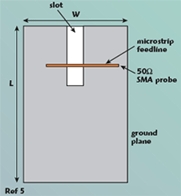
The geometry of the proposed antenna is shown in Figure 2. The antenna is printed on an FR4 substrate with a thickness h = 0.8 mm, a relative permittivity εr = 4.4 and dimensions L1 and W1. The open slot consists of one open-ended, x-directed slot of length W2 and one open-ended, z-directed slot of length L5, connected together on the right side of the ground plane. The open slot is etched in the ground plane and its location results in the non-symmetric ground. The coupling, between the rectangular conducting plate terminating the open end of the 50 Ω microstrip-line feed and the open slot on the non-symmetric ground, generates the wideband impedance of the small area antenna.
The length of the open-ended, x-directed slot W2 and the length of the open slot, y-directed slot length L5 are the major parameters, which determined the lower resonant mode. The higher resonant mode is excited by adjusting the dimensions of the feed structure. By properly choosing the dimensions of the open-ended, x-directed slot W2 and the open-ended, y-directed slot L5, these two resonant modes can be coupled to provide a wide impedance bandwidth. The location of the rectangular conducting plate is close to the end edge of the open-ended, x-directed slot of length W2, which generates a good impedance matching of the proposed antenna. The center length of the open slot (approximately 32.5 mm) is approximately a quarter-wavelength in free space at 2.2 GHz.

Parametric Study and Discussion
The parametric study supplied helpful information to the antenna designers. It included the dimensions of the slot, the rectangular plate and the ground plane. Through these investigations, an optimal design is obtained, suitable for mobile wireless communication products in WLAN, Bluetooth and UWB.
Different Values of Rectangular Plate Width W3
Figure 3 shows the return loss for different widths of the rectangular patch W3. The other antenna dimensions are L1 = 35 mm, L2 = 7 mm, L3 = 14 mm, L4 = 6 mm, L5 = 14 mm, W1 = 30 mm, W2 = 18.5 mm, W4 = 1.53 mm and W5 = 5 mm. As W3 increases, the impedance bandwidth moves to a high frequency. It shows that the bandwidth is not very sensitive to W3.

Different Values of Slot Width L4
Figure 4 shows the return loss with different widths for slot L4 from 2 to 8 mm, with the other dimensions L1 = 35 mm, L2 = 7 mm, L3 = 14 mm, L5 = 14 mm, W1 = 30.mm, W2 = 18.5 mm, W3 = 6 mm, W4 = 1.53 mm and W5 = 5 mm. The results indicate that the bandwidth is very sensitive to L4. When L4 = 6 mm, a broader impedance bandwidth occurs. From these results, the dimension L4 of the slot is set at 6 mm.
Different Values of Slot Width W5
Figure 5 shows the return loss with different widths for slot W5. The other dimensions are L1 = 35 mm, L2 = 7 mm, L3 = 14 mm, L4 = 6 mm, L5 = 14 mm, W1 = 30 mm, W2 = 18.5 mm, W3 = 6 mm and W4 = 1.53 mm. It shows that the bandwidth is more sensitive to W5 than to W3. The symmetric structure (slot W5 = 0 mm) exhibits a dual-frequency characteristic. However, the impedance matching at the higher frequency is not sufficient. With the slot W5 added, a higher resonant mode is excited, which couples to the lower resonant mode to create a wide impedance bandwidth.

Different Dimensions of the Ground Plane, L1 and W1
The measured return loss for different sizes of the ground plane is shown in Figure 6, with L2 = 7.5 mm, L3 = 14 mm, L4 = 6 mm, L5 = 14 mm, W2 = 19 mm, W3 = 6 mm, W4 = 1.53 mm and W5 = 5.5 mm. For the case with the ground plane dimensions L1 = 80 mm and W1 = 50 mm, the bandwidth obtained is more than 90 percent, which is larger than those shown in Table 1. Since the purpose of this work is to broaden the impedance bandwidth of an open slot antenna with a small size, it is observed that the broadband impedance bandwidth operation of the proposed design can be sustained with a small size ground plane of dimensions 35 × 30 mm.
Optimized Design

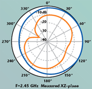
From these investigations, an optimized wideband slot antenna with small dimensions, 35 × 30 mm, can be obtained. The optimized parameters are εr = 4.4, h = 0.8 mm, L1 = 35 mm, L2 = 7.5 mm, L3 = 14 mm, L4 = 6 mm, L5 = 14 mm, W1 = 30 mm, W2 = 19 mm, W3 = 6 mm, W4 = 1.53 mm and W5 = 5 mm. Figure 7 shows the measured and simulated return loss of the proposed antenna. The measured data agree with the simulated data. The wide impedance bandwidth of the proposed antenna is approximately 94 percent (2.2 to 6.1 GHz), as determined from a 10 dB return loss, which is suitable for Bluetooth (2.4 to 2.4835 GHz) and WLAN (2.4 to 2.4835 GHz, 5.15 to 5.35 GHz and 5.725 to 5.850 GHz), and for the low band UWB (3.1 to 5.15 GHz) applications. In addition, the bandwidth obtained with a small size is larger than that of the ones shown in Table 1. Figure 8 shows the measured gain of the proposed antenna. The gain variation over the operating bandwidth of the proposed design is less than 3.08 dB. The measured radiation patterns of the proposed antenna at two typical operation frequencies are also investigated. Figure 9 shows the measured and simulated radiation patterns at 2.45 and 5.2 GHz. At higher frequencies, the radiation patterns of the proposed antenna degenerate because high order modes are excited. These radiation patterns are acceptable for most wireless applications.

Conclusion
This article focuses on the wideband design of a small slot antenna. The coupling between the rectangular conducting plate, which is attached to the open end of the 50 Ω microstrip-line feed, and the λ/4 open slot with the non-symmetric ground, generates a wideband impedance for a small area antenna. The 94 percent impedance bandwidth of the proposed antenna is achieved by using proper dimensions for the open slot and rectangular conducting plate. The overall size of the proposed antenna is 35 × 30 × 0.8 mm. The proposed broad bandwidth, small size antenna is suitable for portable devices in wireless applications.
Acknowledgment
The financial support of this study by the National Science Council, Taiwan Republic of China, under contact number NSC94-2213-E-218-006, is gratefully acknowledged.

References
1. Y.W. Jang, “Broadband Cross-shaped Microstrip-fed Slot Antenna,” Electronics Letters, Vol. 36, No. 25, December 2000, pp. 2056–2057.
2. Y.H. Suh and I. Park, “A Broadband Eccentric Annular Slot Antenna,” 2001 IEEE Antennas and Propagation Society International Symposium Digest, Vol. 1, pp. 94–97.
3. X. Qing, M.Y.W. Chia and X. Wu, “Wide-slot Antenna for UWB Applications,” 2003 IEEE Antennas and Propagation Society International Symposium Digest, Vol. 1, pp. 834–837.
4. Y.F. Liu, K.L. Lau, Q. Xue and C.H. Chan, “Experimental Studies of Printed Wide-slot Antenna for Wideband Applications,” IEEE Antennas and Wireless Propagation Letters, Vol. 3, 2004, pp. 273–275.
5. S.I. Latif, S.K. Sharma and L. Shafai, “Wideband Microstrip Monopole Slot Antenna,” 2003 IEEE International Symposium on Antennas, Propagation and EM Theory, pp. 54–57.

6. S.I. Latif, L. Shafai and S.K. Sharma, “Bandwidth Enhancement and Size Reduction of Microstrip Slot Antennas,” IEEE Transactions on Antennas and Propagation, Vol. 53, 2005, pp. 994–1003.
7. A.P. Zhao and J. Rahola, “Quarter-wavelength Wideband Slot Antenna for 3 to 5 GHz Mobile Applications,” IEEE Antennas and Wireless Propagation Letters, Vol. 4, 2005, pp. 421–424.
8. N. Behdad and K. Sarabandi, “ A Compact Dual-/Multi-band Wireless LAN Antenna,” 2005 IEEE Antennas and Propagation Society International Symposium Digest, Vol. 2B, pp. 527–530.
Wen-Shan Chen received his BS degree in electronic engineering technology from the National Taiwan Institute of Technology (now the National Taiwan University of Technology) and his PhD degree from National Sun Yat-Sen University, Kaohsiung, Taiwan, ROC, in 2001. From 2001 to 2002, he was an assistant professor at the Chien-Kuo Institute of Technology, Changhua, Taiwan, ROC. He is currently an assistant professor of electronic engineering at the Southern Taiwan University of Technology, Tainan, Taiwan, ROC. His research interests include antenna design, RF and microwave circuits.
Kuang-Yuan Ku received his BS degree from the Chung-Chou Institute of Technology, Changhua, Taiwan, ROC, in 2004. He is currently a master student in the department of electronic engineering at the Southern Taiwan University of Technology. His main research interests include printed antennas for wireless communications, especially the wideband slot antenna for WLAN applications.
