

WIRELESS TECHNOLOGY TODAY
Today, data has become a major part of the digital existence. The demand for faster, more reliable and ubiquitous connectivity has reached unprecedented heights. The U.S., home to around 144,000 to 145,000 telecom towers, stands at the forefront of this digital revolution. These towers have long been the backbone of communication networks, facilitating both fixed and mobile communications. However, now the FCC proposes the national fixed broadband standard requiring 100 Mbps for download speeds and 20 Mbps for upload speeds. To support that standard and to continue to enable the demands of ubiquitous connectivity, data throughput speeds must increase. There are various methods to increase wireless telecommunications data throughput speeds and this section will address several of these techniques.
More Channel Bandwidth
It is well known that as the channel bandwidth increases, the data throughput speeds in bits per second also increase. Unfortunately, an increase in bandwidth also increases the effects of noise. For a constant power output, this increase in noise acts to reduce the signal-to-noise ratio (SNR). This, in turn, reduces the modulation index, which reduces the data throughput speed. The net effect is to reduce the spectral efficiency, meaning the increase in data throughput speed is substantially lower than the bandwidth increase would imply. The noise power is determined by the formula in Equation 1.
N=KTB (1)
Where:
N = Noise power (W)
K = Boltzmann’s constant = 1.381 × 10⁻²³ W/Hz/K
T = 290 K at room temperature
B = RF carrier bandwidth (Hz)
Incorporate mmWaves
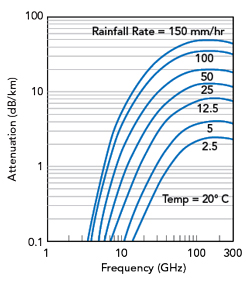
Figure 1 RF signal atmospheric attenuation versus frequency.
Frequencies from 30 to 300 GHz are considered mmWaves. In 5G telecommunications technology, mmWaves are employed to provide high data rates and low latency in wireless communication systems. However, mmWave signals have propagation limitations; they are more susceptible to atmospheric absorption and scattering1 and obstacles like buildings and foliage can disrupt propagation. To compensate for these limitations, networks typically use higher transmission powers and this introduces more noise. In these noisy channel environments, whether the noise is caused by atmospheric absorption, scattering, reflections or if signal sidelobes are interfering, this noise will impair the ability to increase data throughput speeds.
Adding to the challenges, absorption plus scattering caused by hydrometeors2,3 in the transmission medium depolarizes the transmitted radiation. This effect may severely limit system performance, particularly in the case where two orthogonal polarizations are used as separate communication channels. Figure 1 shows a plot of the atmospheric attenuation of RF signals and how this attenuation changes with frequency for various rainfall rates. This shows the effect of absorption and scattering on RF signals in varying rain conditions and the substantial increase in loss per km for the mmWave frequency range is clear.
Increase Modulation Indices

Higher modulation indices, like 64-QAM, 256-QAM or 1024-QAM, increase data throughput speeds but these modulation indices require high SNRs to reap a substantial benefit from the increase in modulation complexity.4 Table 1 shows an example of SNR requirements for different modulation schemes and coding rates. In addition to the atmospheric attenuation of the RF signal, there will also be spreading loss with distance that will depend on the geometry of the transmit/receive antenna array. The effect of these losses will be to reduce the received signal while the interfering noise increases, reducing the SNR. This will decrease the modulation index of the system, reducing the data throughput speeds.
Implement MU-MIMO
Multi-user MIMO (MU-MIMO) is like troposcatter diversity. This technique permits separate data streams to propagate in parallel. Using multiple data streams increases the data throughput speeds with the increase dependent on channel conditions.
Creating multiple antenna beams to transmit multiple data streams means that only a portion of the full phased array antenna is used for each beam.5 This reduces the EIRP of each beam of the communication link. This reduction in antenna gain reduces the SNR and this will reduce the modulation index and decrease the data throughput speeds. These efforts can quickly create a law of diminishing returns situation. Conceptually, the gain reduction experienced with multiple beams from a MU-MIMO antenna system is shown in Figure 2.
A SOLUTION
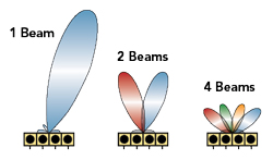
Figure 2 Gain reduction in MU-MIMO system.
The four methods to increase data throughput are all currently in use and enable higher data throughput rates. However, as demonstrated, there are challenges associated with each method. This section provides an alternative solution that avoids or minimizes these challenges. The previous analysis showed that even though an increase in bandwidth increases the throughput speeds, it also increases the noise. As a result, the modulation index decreases to keep the link closed and this reduced spectral efficiency partially negates the benefit of larger bandwidth for data throughput speeds.
The alternative solution that is being developed maintains the same bandwidth in a sector but repeats this bandwidth multiple times within the sector. The bandwidth reuse scheme behaves similarly to an increase in bandwidth, but it does not increase the noise of each of the beams. The net effect is higher data throughput speeds and higher spectral efficiency. Figure 3 shows a rendering of the four-beam radiation pattern in azimuth and Figure 4 shows the simple architecture of this MIMO beamforming network.
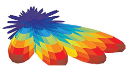
Figure 3 Rendering of a simple four-beam azimuth pattern.
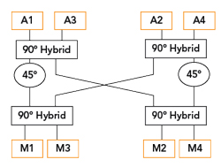
Figure 4 Four-beam MIMO beamforming network.
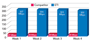
Figure 5 ETI four-beam system speeds versus the original network speeds.
Electromagnetics Technology Industries (ETI) has built and deployed this four-beam MIMO beamforming network. The system uses a 20 MHz channel in a 120-degree sector to provide an average of 28 Mbps data speed in an urban environment. By implementing the four-beam architecture shown in Figure 4 in the same 120-degree sector and repeating the same 20 MHz bandwidth for each beam, data speeds increased by a factor of 10.6 The results of the existing network and the ETI network are presented in Figure 5.
Earlier, the article discussed the signal propagation challenges for signals in the mmWave frequency range. The reason for going to mmWave frequencies was to access wider bandwidth channels to obtain higher data rates, but the bandwidth reuse architecture obviates this need. The ETI system addresses the signal propagation issues by using frequencies below 10 GHz. This earlier section also discussed how absorption plus scattering could depolarize orthogonal transmission signals. U.S. patent 10,141,640 B2 discusses MIMO dual-polarization scenarios and these ideas are fundamental to the ETI architecture.7
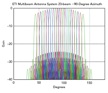
Figure 6 23-beam ETI antenna system with 90-degree azimuth coverage.
Higher modulation indices were shown to increase data throughput speeds, but this increase came with the requirement of higher system SNR values. Achieving these higher SNRs requires higher gain antennas and multiple, narrow beams. Passive and active beamforming networks in azimuth and elevation can easily enable the antenna gain and beam characteristics necessary to support the higher modulation indices.
Finally, the MU-MIMO section presented a method to increase data throughput speeds with multiple bit streams transmitted by an antenna array capable of generating multiple simultaneous beams. When the antenna array generates multiple beams, the gain of each beam is reduced from the gain that would result if all the antenna array radiators were used to produce a single beam. To increase antenna beam gain, beam shaping networks can be added to the beamforming networks mentioned previously.
Figure 6 shows a gain plot for a 23-beam ETI antenna system in a 90-degree azimuth sector. As the plot shows, the sidelobe levels are more than 25 dB from the main lobe as it is steered in its azimuth angle. Figure 6 also shows the gain reduction at the edges of the 90-degree scan from broadside. This gain reduction as the beam is scanned from broadside can be corrected by proprietary and patented techniques.