

Figure 7 shows the results of implementing these proprietary and patented techniques. From the results, we see that the sidelobe levels have been reduced to more than 38 dB below the main lobe with constant beamwidth. These sidelobe levels remain roughly constant as the antenna is scanned along its azimuth angle.
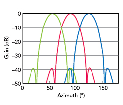
Figure 7 Sidelobe reduction techniques.
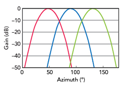
Figure 8 Improved sidelobe reduction technique.
Figure 8 shows a second technique that reduces sidelobe levels even more. In this case, the sidelobes are more than 50 dB below the main lobe. Using this technique maintains this sidelobe reduction performance over an even broader azimuth scan angle. The results of Figure 7 and Figure 8 raise the possibility of using these techniques to improve antenna performance enough to increase the modulation index and improve data throughput rates.
TERABIT WIRELESS SOLUTIONS
Enhancing the performance of wireless networks involves increasing the capacity and data throughput speeds provided by wireless base station antennas. This can be done with multiple radiating lobes in both azimuth and elevation to effectively cover a designated geographic volume. Using the proprietary and patented sidelobe reduction techniques described earlier, along with the antenna architecture that the article describes, allows for modulation indices of 256-QAM and 1024-QAM. These techniques, along with repeating the full bandwidth in each beam, can help achieve higher capacity and data throughput speeds. Figure 9 shows a rendering of the radiation pattern of an antenna system that employs beamforming in the azimuth and elevation directions.
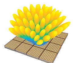
Figure 9 Phased array with multiple beams in azimuth and elevation. Source: courtesy of DARPA.
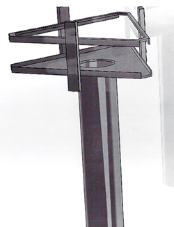
Figure 10 Mounting configuration for three-sector base station.
Examples of the Technology
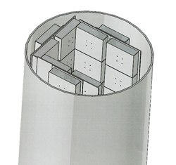
Figure 11 Radios housed inside the tower.
Traditional macrocell tower deployments use three 120-degree sectors. This first example uses three antennas and each antenna has 24 radios. Figure 10 shows a drawing of the tower that supports the antenna and radio infrastructure at a wireless base station.
Figure 11 shows the concept of the radios housed inside a tower for a three-antenna system. For the data results that follow, the radios generate four beams in azimuth and six beams in elevation.
Table 2 shows the maximum speeds available for various channel sizes using 1024-QAM modulation and Table 3 shows the same data for 256-QAM modulation.
The number of radios per antenna can change based on the number of beams that are required. In the following example, the network again has three antennas, but in this case, each antenna has 32 radios. The deployment is the same as shown in Figure 11, but the radios provide four beams in azimuth and eight beams in elevation.

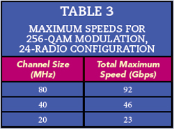
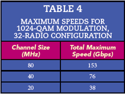
Table 4 shows the maximum speeds available for various channel sizes using 1024-QAM modulation in this new radio configuration and Table 5 shows the same data for 256-QAM modulation.

The practical implications of the architecture are interesting. A network using this architecture with the 32-radio configuration, 1024-QAM modulation and 80 MHz channel bandwidth will provide an aggregate speed of 18.4 Tbps from only 120 telecom towers. To put this into perspective, a geographical area of 348 square miles, roughly the size of Lehigh County in Pennsylvania, can distribute 128.4 Mbps to 143,000 households from these 120 towers. This is without factoring in a contention ratio, but this service still fulfills the U.S. requirements for broadband.
CONCLUSION
This article has compared various methods currently used throughout the industry to increase data throughput speeds. Each one of these methods has advantages and disadvantages. To minimize the disadvantages of these techniques, the article has also presented a simple solution based on a cascadable radio architecture that uses passive beamforming networks, along with proprietary and patented antenna sidelobe techniques. Results show that data throughput speeds, even in simple cases, can increase substantially. The benefit of this technique is it enables operators to meet emerging broadband requirements more readily. In the words of Leonardo da Vinci, “Simplicity is the ultimate sophistication.”
References
- H.C. Van de Hulst, “Light-scattering by Small Particles,” New York: Wiley, 1957, pp. 28–36.
- J. Howard and N.A. Mathews, “Crosspolarisation of Microwaves due to Rain on a Satellite to Earth Path,” IEEE Trans. Antennas and Propagate, Vol. AP 27, No. 6, November 1979, pp. 890–891.
- G. Brussaard, “A Meteorological Model for Rain-Induced Crosspolarisation,” IEEE Trans. Antennas and Propagate, Vol. AP 24, No. 1, January 1979, pp. 5–11.
- Dr. O. Werther and R. Minihold, “LTE: System Specifications and Their Impact on RF & Base Band Circuits,” Rohde & Schwarz Application Note, 2013.
- E. Björnson, “Basics of Antennas and Beamforming-Massive MIMO Networks,” 2018, Web: https://www.youtube.com/watch?v=xGkyZw98Tug.
- J. Howard, “World’s First Wireless Fiber,” The North Jersey IEEE MTT/AP Societies 37th Annual Symposium and Mini-Show, October 4, 2023.
- J. Howard, “Isolation of Polarizations in Multi-Polarized Scanning Phased Array Antennas,” US 10, 141, 640 B2, 27, November 2018.