A novel high gain Q-band reflectarray antenna is designed is designed to work from 39 to 40 GHz for mmWave sensing applications such as mmWave radars. The planar reflecting surface with an area smaller than 10 x 10 cm2 is suitable for mounting on a wireless system of a moving vehicle such as an urban air mobility (UAM) vehicle or LEO satellite. The surface comprises metamaterial-inspired cells compensating for the spherical wavefront of a feed horn to produce a planar wavefront in reflection. An antenna gain greater than 21 dBi in a palm-sized planar antenna enables high resolution and high data rate transmission. An asymmetric feed mitigates blockage error. The antenna is also low cost and built with inexpensive fabrication techniques and materials.
With the advent of 5G mobile service plans comes the vision of hyper-connectivity and low latency.1 Connectivity is expected to transcend the boundaries of legacy mobile services through the IoT.2 The scenario of New Radio (NR) is expanded to involve UAM and LEO satellites as nodes of non-terrestrial networks (NTNs).3 Fast data transmission, dubbed as low latency in mobile networking, was introduced with mmWaves. Because of its broadband capability, high capacity and low latency are possible.4
Automated car platooning and unmanned delivery by air have been discussed and modeled with the use of onboard mmWave radar technology, for example, UAM vehicles and LEO satellites.5,6 To meet the required functionality, vehicles must have light sensor payloads for fuel efficiency and agility. To comply with flight safety regulations, precise flight control and collision avoidance capabilities are necessary; wireless sensors must be technologically advanced for high accuracy and fast data acquisition and sharing.
When it comes to the wireless payload, monopole and parabolic reflector antennas are popular for data transmission. Monopoles connect a mobile platform with the radio infrastructure over a wide area with an omnidirectional far-field radiation pattern. For long distances, faster communication and higher directivity, parabolic reflector antennas provide highly directional beam patterns.7 However, it is relatively costly to manufacture, stow, deploy and maintain a conventional curved metallic parabolic antenna structure.
An alternative is the planar reflectarray but, like the parabolic reflector antenna, can also convert a spherical wave to a plane wave.8 Martinez-de-Rioja et al.9 fabricated a reflectarray unit cell as parallel metal strips on two dielectric substrates and replicated it to 900 elements. The lengths of the metal bars in the reflectarray were individually tuned to operate at 20 GHz. Yamai et al.10 reported on a reflectarray whose impedance matching occurs at 23.86 GHz. The 1600-element antenna had a gain of 21.18 dBi. Zhao et al.11 built a three-layered surface-based dual-reflectarray antenna for a monopulse radar at 35 GHz. The sensing device had a sum-mode antenna gain of 29.4 dBi enabled by a sub-reflecting surface of 16 x16 elements as well as a primary reflector of 56 x 56 elements. A 74 GHz band reflectarray was proposed by Al-Nuaimi et al.12 A 3.24 mm thick Arlon® AD1000 substrate (εr = 10.75) with air-holes was used for the phasing of 41 x 41 elements. Miao et al.13 described a 400 GHz reflectarray antenna. Phasing for this sub-terahertz antenna was realized by the reactive ion etching and sputtering of gold metal patterns on a quartz substrate.
In this article, a small single layer reflectarray antenna with high gain is described for operation at mmWave frequencies. Potential applications are 5G wireless communication and sensing devices like collision avoidance radars. Normal incidence leading to normal reflection as well as asymmetric reflection from an offset feed is realized with a 26 x 26 element reflectarray on a 5 mil. thick TLY-5 substrate. It is inexpensive to form the etched metal patterns and the array size is less than 10 x 10 cm.
The reflecting substrate is mounted on an acrylic fixture facing a feed horn with an F/D of 0.5. Measurement reveals good impedance matching, highly directional beam patterns and an antenna gain of over 21 dBi at 39.5 GHz for normal reflection (θ = 0 degrees on the φ = 90-degree plane) and asymmetric reflection (θ = 15 degrees on the φ = 90-degree plane).
DESIGN FOR THE CASE OF NORMAL REFLECTION
Figure 1 shows a parabolic antenna replaced by a reflectarray metasurface. The curved reflecting surface of the parabolic antenna is imitated with a flat reflecting surface, which is a grid of phasing cells that compensate for the different delays of incident rays from the horn.

Figure 1 Replacement of a parabolic reflector with a reflectarray.
For on-vehicle sensing or 5G backhaul antennas, the reflectarray antenna should satisfy specifications such as those listed in Table I.

Parabolic Reflector Antenna Baseline
Before addressing the reflectarray design, the performance of a parabolic reflector antenna is established as a baseline for comparison. The parabolic reflector antenna is a metallic structure (see Figure 2a). Its diameter is approximately 7 cm for operation in Q-Band and is comparable in size to a 5G in-building access-point antenna. It is fed by a standard horn antenna as the primary feed. Boundary conditions for a perfect electrical conductor are applied to the metallic body.15 As F/D varies from 0.3 to 0.5, the gain of the parabolic reflector is expressed as the curves in Figure 2b. Gain is lower for F/Ds of 0.35 and 0.4. For an F/D of 0.5, the simulated far-field pattern with 24 dBi gain at 39.75 GHz is shown in Figure 2c. This is used for comparison with the reflectarray.
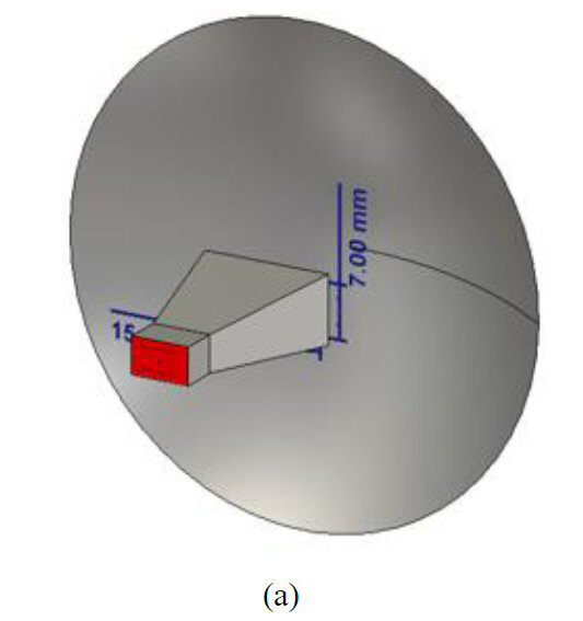
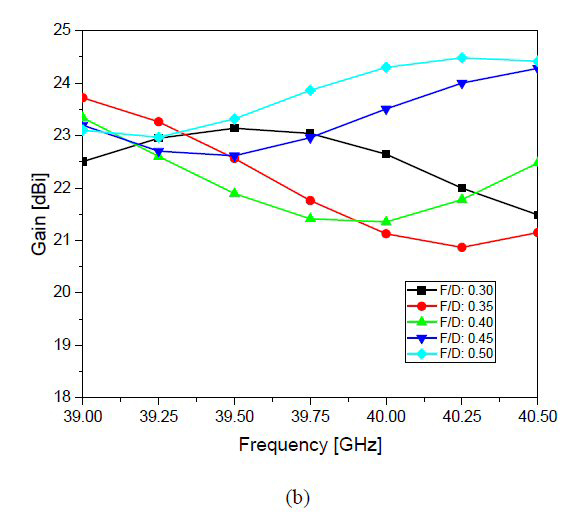
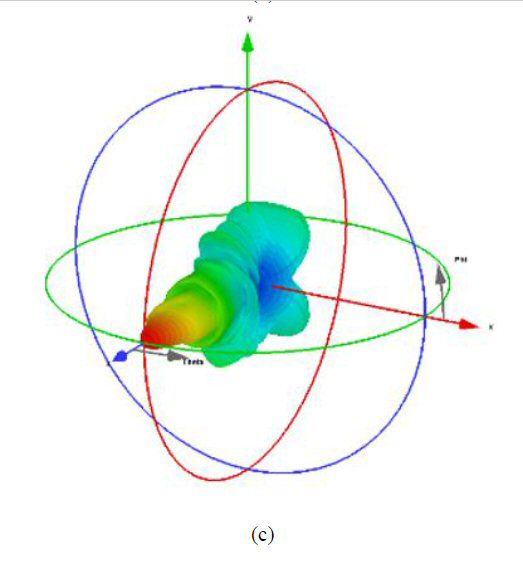
Figure 2 Parabolic reflector antenna geometry (a), simulated gain as a function of frequency and F/D (b) and simulated far-field 3D antenna pattern (c).
The feed horn geometry (see Figure 3a) is compliant with WR-22 waveguide. The physical dimensions are entered into the EM simulation. The reflection coefficient magnitude over frequency, |S11| (see Figure 3b) shows wideband performance. The simulated radiation pattern (see Figure 3c) is broader than the highly directional beam of Figure 2c. The simulated antenna gain of the primary feed is 12 dBi at 39.75 GHz.
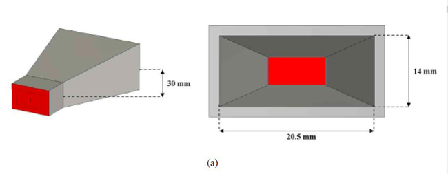
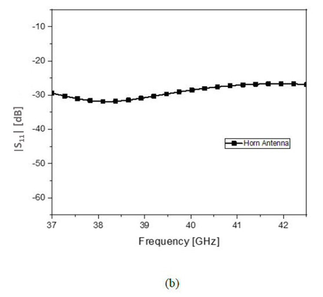
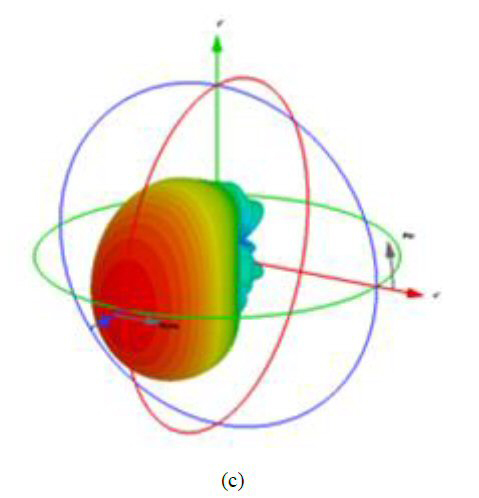
Figure 3 Primary feed: horn antenna dimensions (a), |S11| (b) and far-field pattern (c).
Reflectarray Antenna
As previously mentioned, the reflectarray is a grid of unit cells. The phase distribution required by the reflecting surface for transforming a spherical incident wave from the feed horn to an outbound plane wave is initially expressed as continuous; but, for realization, it is discretized.
The phases of the discrete cells can be realized as fine or coarse geometries. The use of a three-bit geometry is the fine approach, while a one-bit geometry is the coarse approach. A 3-bit metal pattern will assure high accuracy, but it takes longer to simulate and requires more memory. For the sake of simulation time and practicality, a 1-bit approach is chosen here.
A single bit represents just two phase states, 0 and 180 degrees. A rectangular patch can produce two phases in one cell (see Figure 4). The physical dimensions, x0 and x1, are shown in Figure 4c to produce phases of 0 or 180 degrees as they are varied from 0.33 to 0.60 λ and from 2.2 to 2.5 mm, respectively.
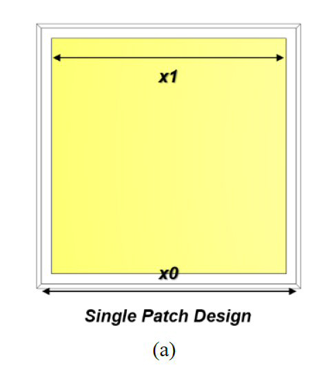


Figure 4 A unit cell and its characteristics for a 1-bit reflectarray: top view (a), side view (b), geometry versus phase state (c).

