

Figure 5a shows the desired phase distribution of the reflectarray for normal reflection. Figure 5b corresponds to its 1-bit approximation. A bird’s eye view, where the horn antenna feeds the planar reflecting surface, is shown in Figure 5c. A high directional beam pattern is simulated as shown in Figure 5d. Figure 5e shows |S11| of the simulated feed with and without the reflector. The simulated reflectarray antenna has a gain of about 23 dBi, almost the same as the reference structure and greater than that of the feed horn by about 11 dB (see Figure 5f).
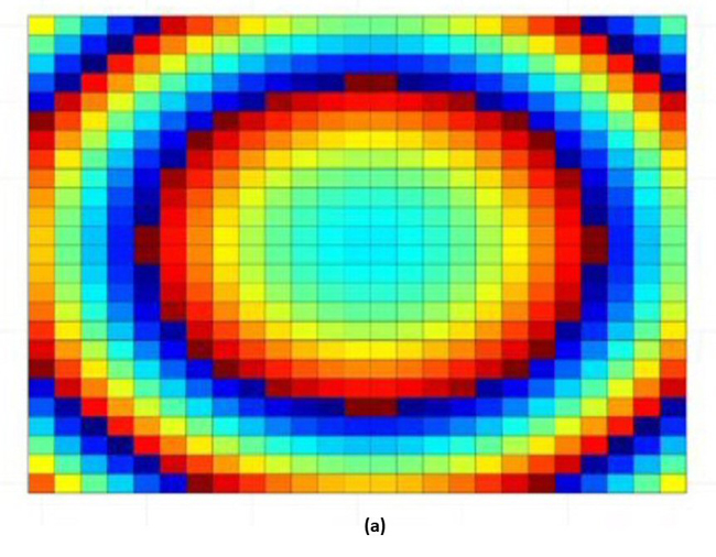
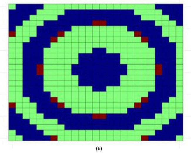
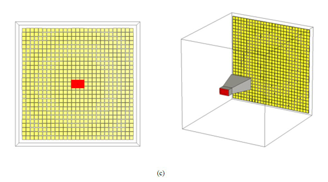
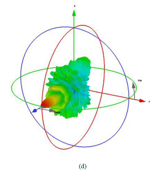
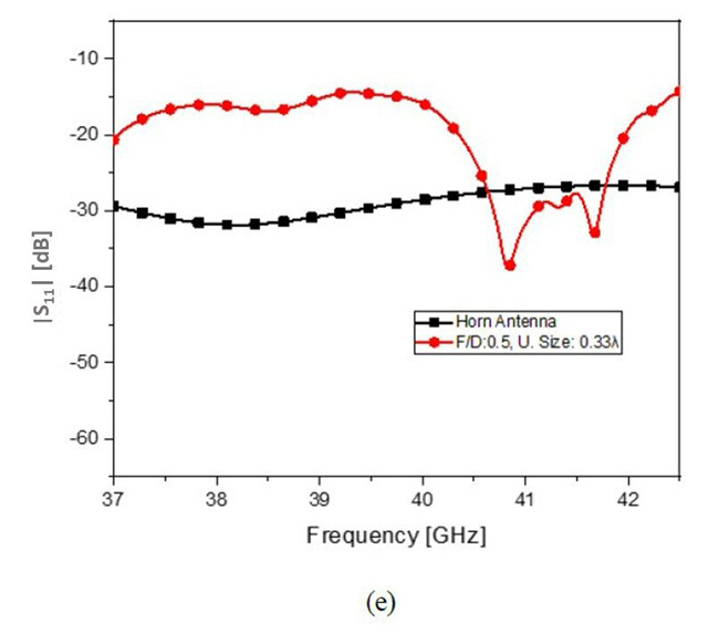
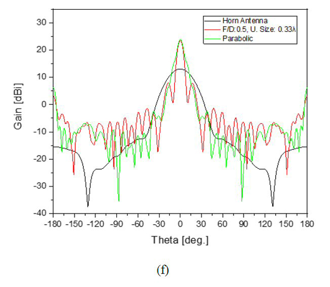
Figure 5 The 1-bit reflectarray for normal reflection: desired phase distribution (a), 1-bit discrete approximation (b), structure 3D view (c), 3D reflectarray simulated beam pattern (d), |S11| of the simulated horn feed with and without the reflector (e) and far-field simulated azimuth antenna patterns over frequency (f).
Assembly and Measurement
The feed horn is shown in Figure 6a. Its measured |S11| is less than - 10 dB (see Figure 6b). The discrepancy between the simulated performance and measured data is likely due to interfaces and differences in the hardware versus parameters used in the EM simulation. The measured far-field pattern is very similar to the simulation (see Figure 6c). The antenna gain of the modeled feed horn in Figure 5f is about 12 dBi with a half-power beamwidth of approximately 30 degrees. This is in good agreement with the measured values in Figure 6(c).
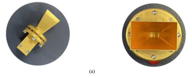
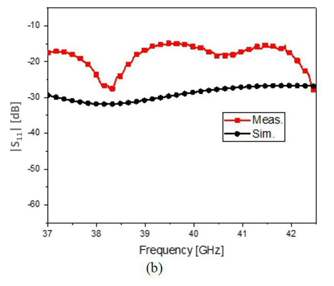
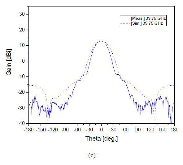
Figure 6 Reflectarry antenna feed horn: top and front views (a), measured versus simulated |S11| (b) and measured versus simulated far-field pattern (c).
Figure 7a is the reflectarray surface comprising two types of copper cell patterns. |S11| is plotted in Figure 7b for the case where the horn illuminates the reflectarray surface (see Figure 7c). Radiated far-field antenna patterns are shown in Figure 7d.
The antenna patterns for seven frequency points across the frequency band of interest look very similar. The radiation pattern at 39.75 GHz demonstrates a gain of 23 dBi. The angle of the main beam is shifted by about 10 degrees. This is attributed to an uneven reflecting surface; there are some spots with air gaps between the bottom of the groove of the jig and the backside of the reflectarray. This can be corrected in the future with an improved mounting method.
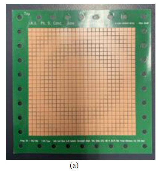
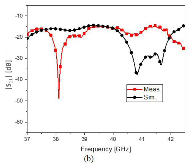

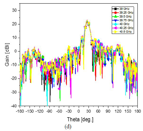
Figure 7 Prototype 1-bit reflectarray antenna designed for normal reflection (a), measured |S11| versus simulation (b), test setup (c) and measured far-field azimuth antenna patterns over frequency (d).