

A novel dual-band radio frequency identification (RFID) reader antenna for the industrial, scientific and medical (ISM) bands at 2.4 and 5.8 GHz is fabricated on a low cost 1.5 mm FR4 substrate with a 4.3 relative permittivity and 0.025 loss tangent. Slots are introduced to reduce its dimensions and achieve dual-band performance. The dimensions are just 34 × 34 × 1.5 mm, so it is easily integrated into RFID readers. Experimental results show good agreement with simulation.
RFID encodes, or stores, digital data onto RFID tags (also known as RFID transponders). An RFID transponder is affixed to an object to enable remote tracking. In contrast to bar code technology, which requires that codes printed on a label pass in direct view of an optical reader, RFID tags can be read at a distance without a direct line of sight. The ease and speed of this technology makes it suitable for applications where the reading of bar codes slows down the information acquisition process.
The RFID system comprises an RFID tag and an RFID reader. The RFID tag contains an integrated circuit connected to an antenna and is encapsulated in a protective shell. The RFID reader is a receiver and transmitter controlled by a microprocessor or a digital signal processor. An antenna connected to the reader “captures” the data stored in the tag for processing.1,2
RFID systems operate in several assigned bands. There are bands at low frequency around 125 kHz, high frequency around 13.56 MHz, ultra-high frequency from 860 to 960 MHz and microwave around 2.45 or 5.8 GHz. The most important RFID system components are the reader and tag antenna. RFID applications require small antennas with high performance (large bandwidth, multi-band operation and high gain).3 There are various methods to realize multi-band operation, such as metamaterial technology,4,5 multilayer substrates,6 fractal technology7 and slot reactive loading.8, 9,10 Slot loading can not only achieve multi-band operation but can also provide broadband performance and miniaturization. Several antennas have been proposed,4-12 however, these are either not compact or are difficult to physically realize.
This work demonstrates a compact, low profile dual-band RFID reader antenna for ISM applications. It features one connection (port), where a two-port dual-band reader antenna puts an additional requirement on sufficient port isolation.13 The design begins with a conventional rectangular microstrip patch antenna. Five C-shaped slots are added for dual-band operation and to improve return loss and gain. Further improvement is achieved in operation at 2.4 and 5.8 GHz with a rectangular slot in the center of the radiating element.
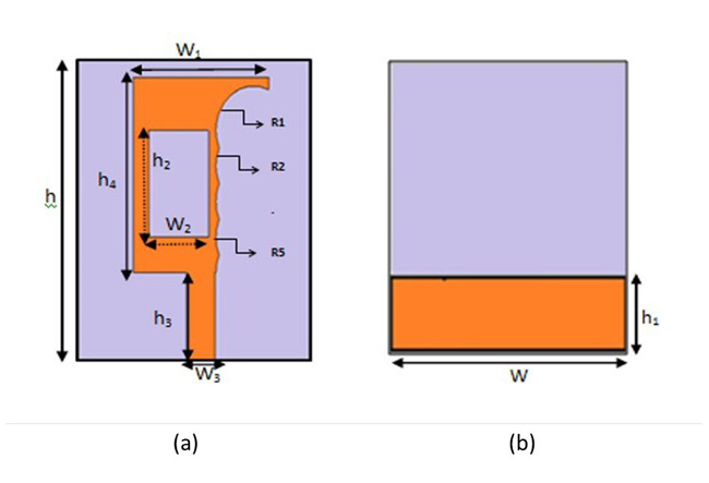
Figure 1 RFID dual-band reader antenna geometry: front side (a) and back side (b).
ANTENNA DESCRIPTION
The structure is shown in Figure 1. It is designed for fabrication on a low-cost FR4 substrate with a permittivity of 4.3, loss tangent of 0.025 and a compact size of (34 × 34 × 1.5 mm3). The radiating patch is connected to a rectangular feed line with a width W3 = 3.89 mm and a length h3 = 10 mm. On the back side of the substrate, a conducting partial ground plane has a width W = 34 mm and a length h1 = 9 mm. The patch and the ground plane are copper with thickness t = 0.035 mm. The antenna is connected to a 50 Ω SMA connector for signal transmission. The width of the microstrip feed line is adjusted to improve impedance matching. Table I shows optimized dimensions of the patch, slots, ground plane and substrate. Several optimizations were conducted using Computer Simulation Technology (CST) software to properly select the dimensions, positions and number of slots.14-16
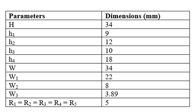
Table 1 RFID antenna optimized dimensions
DESIGN PROCEDURE
A conventional rectangular microstrip patch antenna (ANT1) is designed by applying equations of the transmission line model to resonate around 2.4 GHz in the ISM Band (see Figure 2a).17 A rectangular radiating patch is located on the top side of the FR4 substrate and it is fed with a microstrip line. On the back side of the substrate, a partial ground plane is embedded. Its size and performance characteristics meet RFID system requirements at 2.4 GHz. To achieve dual-band operation, ANT2 adds five C-shape slots (see Figure 2b). This antenna, however, does not resonate at the desired frequencies. The final design (ANT3) adds an internal slot (see Figure 2c) to tune the antenna to operate in the desired bands. Several optimizations are performed in this process.
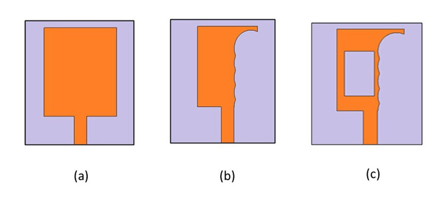
Figure 2 Antenna design evolution: ANT1 (a), ANT2 (b) and ANT3 (c).
Return loss of the three structures as a function of frequency is plotted in Figure 3. The first antenna (ANT1) resonates near the desired frequencies. The second design (ANT2), with five slots, has poor return loss near 5.8 GHz and deviates from the desired resonances at 2.4 and 5.8 GHz. For the final antenna design (ANT3), return loss is improved by adding the rectangular slot and by adjusting its dimension and position along the radiating element. The antenna is tuned to the exact frequencies.

Figure 3 Simulated return loss versus frequency for the three designed antennas: green trace (ANT1), red trace (ANT2) and purple trace (ANT3).
PARAMETRIC STUDY
A parametric study is performed using CST Microwave Studio. The rectangular slot width, length and position are varied to optimize the final design; however, the only parameter having a significant effect is the slot width. Figure 4 shows |S11| as the slot width is increased from 2.5 to 8 mm. Return loss peaks increase with increasing slot width. Numerical results are given in Table II.
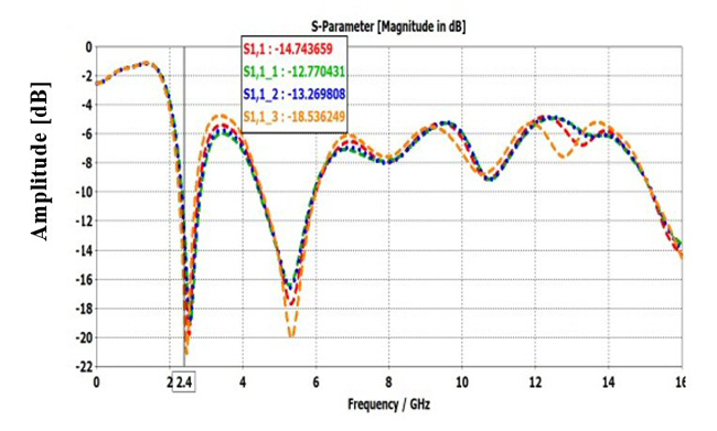
Figure 4 Return loss for different values of W2.
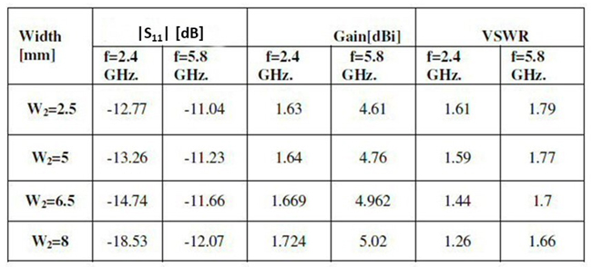
Table 2 Slot width parametric study simulation results
SIMULATION
Simulations are performed to investigate dual-band properties, for example, |S11|, voltage standing wave ratio (VSWR), radiation patterns, gain, efficiency and current distribution.
Figure 5 shows |S11| versus frequency, with |S11| of –18.96 dB and –12.07 dB at 2.4 and 5.8 GHz, respectively. Figure 6 shows the corresponding VSWR as a function of frequency. The simulation shows that the antenna is well matched. VSWRs are 1.26 and 1.66 at the operating frequencies 2.4 and 5.8 GHz, respectively.
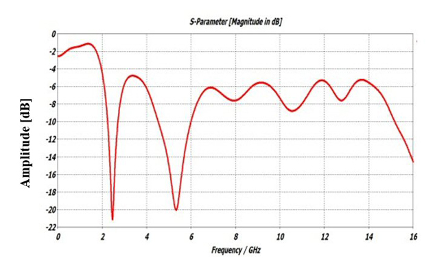
Figure 5 Antenna simulated |S11| versus frequency.
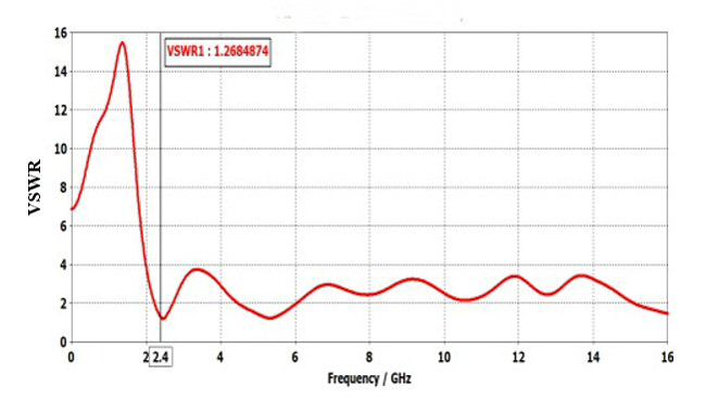
Figure 6 Antenna simulated VSWR.
Figures 7 and 8 are 2D radiation patterns in the E- and H-planes at 2.4 and 5.8 GHz, respectively. Figure 9 shows antenna gains of 1.7 dBi at 2.4 GHz and 5 dBi at 5.8 GHz.
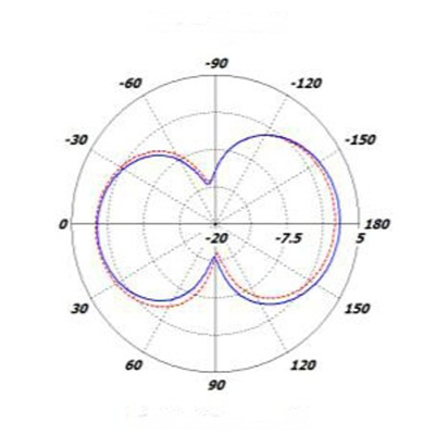
Figure 7 Simulated 2D radiation patterns at 2.4 GHz, blue trace is E-Plane and red trace is H-Plane.
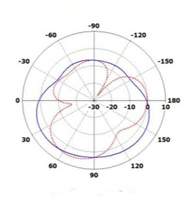
Figure 8 Simulated 2D radiation patterns at 5.8 GHz, blue trace is E-Plane and red trace is H-Plane.
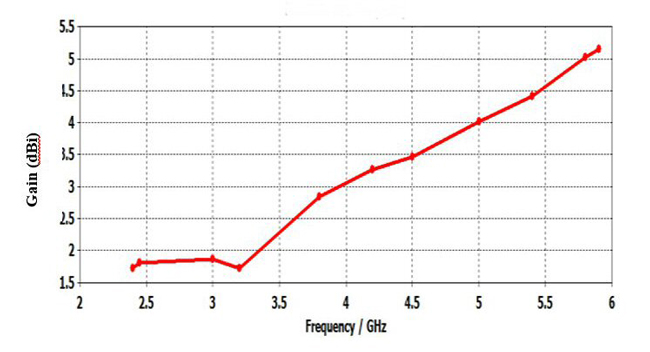
Figure 9 Simulated antenna gain versus frequency.