

TRI-BAND BPF DESIGN
Based on the theory of MSIRs, the tri-band BPF centered at 2.4, 4 and 5.6 GHz is designed (see Figure 1). It comprises two open-end feed lines, a pair of MSIRs and two pairs of OLRRs. The MSIRs determine the first passband center frequency, fractional bandwidth and selectivity. The chosen parameters are: k1= 0.75, k2 = 0.3, l1 = 7.6 mm, l2 = 3.93 mm, l3 = 3.6 mm, l4 = 3.24 mm, l5 = 0.1 mm, w1 = 0.195 mm, w2 = 0.4 mm and w3 = 1.8 mm.
The OLRRs are traditional half wavelength resonators determining the second and third passband responses. The difference is that the OLRRs used in the second passband are meandered. Two extra transmission zeros are produced between the first and second and the second and third passbands. This improves passband isolation and selectivity.
The bandwidths depend on the coupling coefficients and external quality factors. That is, s1, s2, d1 and d2 affect the bandwidths; s1 = 0.4, s2 = 0.6, d1 = 0.1 and d2 = 0.2 mm. The length L of the open-end feed line is about a half wavelength at the first operating frequency of 2.4 GHz and the impedance is 50 Ω. Here L = 30 and w = 0.5 mm.
Figure 5 shows the current distribution of the feed line at 2.4, 4 and 5.6 GHz. The resonators are placed at positions of maximal current distribution for strong magnetic coupling.
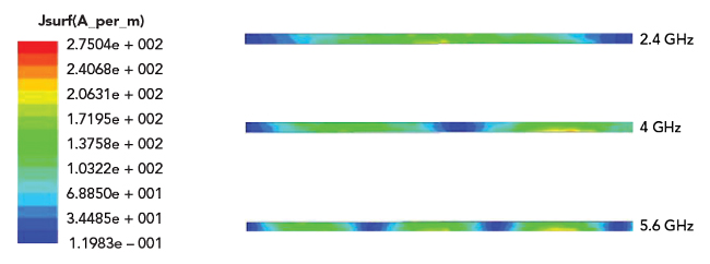
Figure 5 Current distribution of open-ended feed line.
The filter is fabricated on a substrate with a relative permittivity of 9.6 with a dielectric height of 0.5 mm. The overall size of the filter is 30 × 9 mm.
RESULTS AND DISCUSSION
The tri-band BPF (see Figure 6) is simulated using ADS Momentum and measured using a Keysight 8719ES network analyzer (see Figure 7). Measured results show good agreement with the simulation. The passbands are centered at 2.4, 4 and 5.6 GHz with 3 dB bandwidths of 5.9, 44 and 22.4 percent, respectively, with insertion loss less than 1.1, 0.8 and 0.1 dB. The locations of transmission zeros are at 2.72, 3.2, 3.68, 4.35, 4.8 and 6.6 GHz, providing rejection greater than 35 dB.
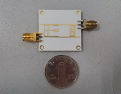
Figure 6 Tri-band BPF photograph.
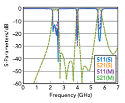
Figure 7 Tri-band BPF simulation and measurements.
Table 1 compares this performance with other work, showing that this filter contains the most transmission zeros and the best isolation between passbands.

CONCLUSION
A novel tri-band BPF combines MSIRs and OLRRs. The proper impedance ratios and electrical lengths of the MSIRs realize a wide upper stopband. The meander OLRRs produce two extra transmission zeros at the upper and lower sides of the second passband, which improves band-to-band rejection. Consequently, the low-cost tri-band BPF is only 30 × 9 mm2 with operating frequencies at 2.4, 4 and 5.6 GHz. The insertion loss of each band is less than 1.1 dB and band-to-band rejection is better than 35 dB. High selectivity, compact size and low insertion loss makes it attractive for use in 5G applications.
References
- B. Ren, Z. Ma, H. Liu, X. Guan, P. Wen and M. Ohira, “Compact Multi-Band Differential Bandpass Filters Using Microstrip Multi-Mode Resonators,” IEEE MTT-S International Wireless Symposium, May 2019.
- V. N. Rahangdale and J. Sengupta, “Stub-Loaded Resonators Application in Ultra Compact Multi-Band Bandpass Filter,” 9th International Conference on Computing, Communication and Networking Technologies, July 2018.
- H. Liu, R. Wang, C. Lai, H. Li and Z. Zuo, “A Compact Quint-Band Bandpass Filter with High Selectivity Using Uniform Impedance Resonators,” IEEE MTT-S International Microwave Workshop Series on Advanced Materials and Processes for RF and THz Applications, July 2020.
- L. -C. Tsai and C. -W. Hsue, “Dual-Band Bandpass Filters Using Equal-Length Coupled-Serial-Shunted Lines and Z-Transform Technique,” IEEE Transactions on Microwave Theory and Techniques, Vol. 52, No. 4, April 2004, pp. 1111–1117.
- C. -Y. Chen and C. -Y. Hsu, “A Simple and Effective Method for Microstrip Dual-Band Filters Design,” IEEE Microwave and Wireless Components Letters, Vol. 16, No. 5, May 2006, pp. 246-248.
- X. Lai, B. Wu, T. Su and C. -H. Liang, “A Novel Tri-Band Filter Using Stub-Loaded Open Loop Ring Resonators,” Microwave and Optical Technology Letters, Vol. 52, No. 3, March 2010, pp. 523–526.
- C. -F. Chen, “Design of a Compact Microstrip Quint-Band Filter Based on the Tri-Mode Stub-Loaded Stepped-Impedance Resonators,” IEEE Microwave and Wireless Components Letters, Vol. 22, No. 7, July 2012, pp. 357–359.
- A. Neogi and J. R. Panda, “Dual-Band Filter with Centrally Loaded SIR and DGS for WLAN Applications,” 4th International Conference on Electronics, Communication and Aerospace Technology, November 2020.
- C. Chen, T. Shen, T. Huang and R. Wu, “Design of Multimode Net-Type Resonators and Their Applications to Filters and Multiplexers,” IEEE Transactions on Microwave Theory and Techniques, Vol. 59, No. 4, April 2011, pp. 848–856.
- J. S. Hong, Microstrip Filters for RF/Microwave Applications, Second Edition, Wiley, 2011.
- B. A. Kumar and O. P. Meena, “Design & Simulation of a Compact Multi-Band Microstrip Bandpass Filter using C shaped Stub-Loaded Resonators,” IEEE Students Conference on Engineering & Systems, July 2020.
- S. Lan, M. Weng, S. Chang, C. Hung and S. Liu, “A Tri-Band Bandpass Filter with Wide Stopband Using Asymmetric Stub-Loaded Resonators,” IEEE Microwave and Wireless Components Letters, Vol. 25, No. 1, January 2015, pp. 19–21.