

A tri-band microstrip bandpass filter is designed for 5G applications. It uses multi-mode stepped-impedance resonators (MSIRs) and open loop ring resonators (OLRRs). By controlling the impedance ratio and electric length of the MSIRs, higher resonant modes are suppressed out of band. The meander OLRRs produce two extra transmission zeros in the upper and lower sides of the second passband that provide good isolation between passbands. A high performance passband response is demonstrated with a small shape factor and low insertion loss. Measured results show good agreement with simulation.
With the rapid development of modern wireless communication systems, the multi-band filter has become a critical circuit component for versatile 5G applications. Much work has been done on the design of multi-band filters with low loss and high selectivity.1-3
There are several approaches. In the work of Tsai and Hsue,4 a bandpass filter (BPF) and a bandstop filter were cascaded to realize a dual-band BPF. It results in a large circuit size, however, and requires additional external matching networks as well. The use of OLRRs and stub-loaded OLRRs5,6 is a simple and effective method for multi-band filter design. Unfortunately, higher-order modes are easily excited. Stepped-impedance resonators (SIRs), characterized by controlling higher-order modes conveniently, are also typically used;7-9 however, poor isolation between passbands and complexity are major disadvantages.
In this work, a novel tri-band microstrip BPF is designed based on a simple and effective method. The filter comprises two open-end microstrip lines, a pair of MSIRs and two pairs of OLRRs (see Figure 1). The MSIRs tune the higher-order modes and higher-order upper stopband. The meander OLRRs, provide greater skirt selectivity with two extra transmission zeros.
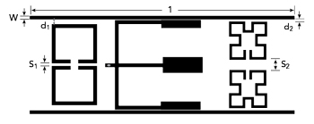
Figure 1 Tri-band filter schematic layout.
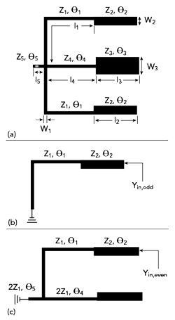
Figure 2 MSIR structure (a), even-mode equivalent circuit (b) and odd-mode equivalent circuit (c).
RESONATOR ANALYSIS
The OLRRs and meander OLRRs have been analyzed by Hong,10 therefore, only the MSIRs will be reviewed theoretically here. Figure 2a shows the MSIR structure. Even-odd mode analysis can be used due to its symmetry. Figure 2b is the even mode equivalent circuit and Figure 2c is the odd mode equivalent circuit.
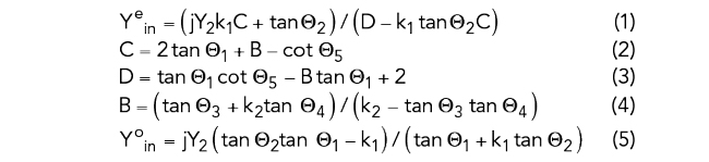
The input admittances for even and odd modes can be expressed by Equations (1) and (5).
Here, l1, l2, l3, l4 and l5 are the lengths of each stub with impedances z1, z2, z3, z4 and z5. The corresponding electrical lengths of the stubs are θ1 = β1l1, θ2 = β2l2, θ3 = β3l3, θ4 = β4l4 and θ5 = β5l5. The impedance ratio k1 = z2/z1 and k2 = z3/z1. The resonant condition of the MSIRs is when the input admittance equals zero, namely, Ye = Yo = 0. Then:
As shown in Figure 3, the first even mode (f1even) and the first odd mode (f1odd) resonant frequencies can be tuned by changing the impedance ratio k1. The impedance ratio k2 mainly influences the second even mode (f2even). Figure 4 shows that f1even and f2even also depend on the lengths of l3 and l5, respectively. The resonator can then be determined by properly choosing these parameters.
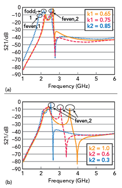
Figure 3 Operating frequencies as a function of impedance ratios k1 (a) and k2 (b).
Figure 4 Operating frequencies as a function of lengths l3 (a) and l5 (b).