

77 GHz Air Cavity-Backed Series-Fed Patch Antennas
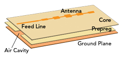
Figure 8 Exploded view of the air cavity-backed series-fed patch antenna array.
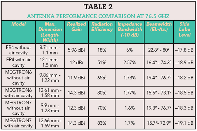
A series-fed patch array is one of the most common types of antennas used in 77 GHz automotive radars. These antennas provide a wide beamwidth in the azimuth plane to enlarge the field of view and a narrow beamwidth in the elevation plane to suppress the ground clutter. Typically, the antenna array is fed by a microstrip line on the top layer with the ground plane located on the bottom layer. In this work, an air cavity is created in the prepreg layer between the top and bottom layers as shown in Figure 8. Antennas are designed using different materials and with/without air cavities to make the comparison. For the stack-ups without an air cavity, the dielectric thickness is chosen as 127 μm. In the stack-ups that contain an air cavity, a total thickness of 133 μm is used. The air cavity width is set to 2000 μm, while the cavity thickness is 58 μm. As seen in Table 2, the air cavities increase antenna performance at the expense of larger size. The larger dimensions result from the reduction in the effective dielectric constant. With no air cavity, the antenna on the FR4 has very poor gain and efficiency. The conclusion is that even though it has a large impedance bandwidth, FR4 alone is not suitable for this application. Forming an air cavity in the FR4 stack-up provides more than 6 dB higher gain and 33 percent better radiation efficiency. The antenna performances on the MEGTRON6 and MEGTRON7 are similar. In both cases, air cavities increase the antenna gain by roughly 2 dB and efficiency by 15 percent, while increasing the antenna dimensions by 28 percent.
5G mmWave Air Cavity-Backed Antenna Demonstrator
This example describes a 28 GHz aperture-coupled patch antenna array with an air-filled cavity in the substrate.6 The stack-up consists of a core and a prepreg material using MEGTRON7 (Dk=3.34, Df=0.0037) with a thickness of 127 μm and Doosan (Dk=4.5, Df=0.016) with a thickness of 80 μm. The three cores are stacked with the two prepregs in a high temperature lamination process. The air cavity is produced in advance of the pressing cycle by laser cutting. The dimension of the air cavity is chosen to be sufficiently larger than the patch so that the impact from fringing fields becomes negligible. It is worth noting that the Doosan prepreg material has a no-flow property. This is because the prepreg material can flow into the air cavity region and has been left as residuals that may cause significant degradation of the radiation performance. The patch dimension is 4.5 mm in width and 3.6 mm in length. The length of the open stub in the microstrip feed line and the aperture on the ground are adjusted so that the antenna resonates at 28.5 GHz. With these patch dimensions and this configuration of the antenna substrate, a single patch antenna achieves a realized gain of 9.3 dBi.
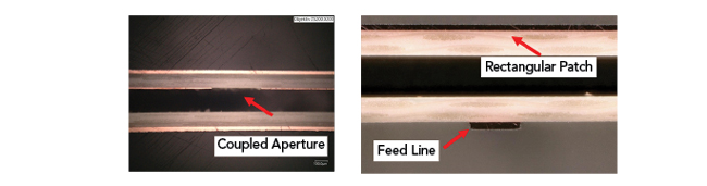
Figure 9 Cross-section of the fabricated air cavity-backed ACPA.
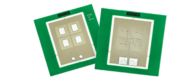
Figure 10 28 GHz air cavity-backed aperture-coupled patch antenna array.
As a demonstrator, we fabricated an ACPA array with four radiators. The cross-section of the stack-up and a picture of the fabricated array are shown in Figure 9 and Figure 10, respectively. The S-parameters of the demonstrator were measured using a Rohde & Schwarz vector network analyzer and the far-field radiation pattern was measured in an anechoic chamber. Figure 11 and Figure 12 show the measured return loss and the radiation patterns at 28 GHz, which are compared to numerical simulation results. The antenna had a realized gain of 14.8 dBi with a 10 dB impedance bandwidth of 3.8 percent with a substrate thickness of 0.035 λ0.
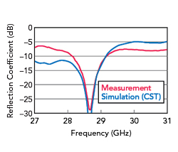
Figure 11 Measured and simulated return loss of the air cavity-backed ACPA.
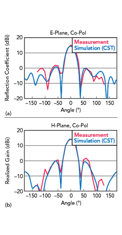
Figure 12 Radiation patterns of the air cavity-backed ACPA at 28 GHz.
CONCLUSION
Creating an air cavity in the PCB stack-up decreases the insertion losses of the traces and increases the antenna performance in the mmWave bands. The effectiveness of the air cavity depends on the cavity dimensions and dielectric material type. To realize these benefits, the air cavity dimension needs to be sufficiently larger than the traces or radiators so that the impact from fringing fields becomes negligible. 5G mmWave modules and 77 GHz automotive radars are some of the applications that can benefit from the improved performance of antenna substrates that use air cavities. To demonstrate the implementation of this concept, we fabricated and measured a 28 GHz aperture-coupled patch antenna. This antenna achieved a realized gain of 14.8 dBi and 10 dB bandwidth of 3.8 percent.
References
- T.E. Bogale, X. Wang and L.B. Le, “mmWave Communication Enabling Techniques for 5G Wireless Systems,” mmWave Massive MIMO, Elsevier, 2017, pp. 195–225.
- 3GPP, “NR; User Equipment (UE) Radio Transmission and Reception; Part 1: Range 1 Standalone. 38.101-1,” Release 15, March 2019.
- S.M. Patole et al., “Automotive Radars: A Review of Signal Processing Techniques,” IEEE Signal Processing Magazine, 34.2, March 2017, pp. 22–35.
- K. Rana and P. Kaur, “Comparative Study of Automotive Sensor Technologies Used for Unmanned Driving,” 2021 2nd International Conference on Computation, Automation and Knowledge Management (ICCAKM), January 2021, pp. 346–350.
- D.M. Pozar, “Microwave Engineering,” Wiley, Ed. 4, 2012.
- H. Takahashi et al., “Air-filled Cavity-backed 28 GHz Antenna Array Implemented by 2.5D PCB Process and Network Analysis,” 51st European Microwave Conference (EuMC), April 2022, pp. 534–537.