
With commercial 6G networks on target to launch in 2030, the race is on to harness radio technologies that can deliver lower latency, higher capacity and enhanced spectrum sharing. Specifications for 6G and most crucially, the optimal adoption of distributed radio access networks, push beyond 5G’s gigahertz (GHz) technologies. One possibility to enable this leap in performance is stepping up to terahertz (THz) frequencies. THz science occupies the frequency range between microwave electronics and photonics. This area has attracted increasing interest during the past two decades and now targets the exciting opportunities that exist in sensing, imaging and data communications. Since the pioneering work to create a link between the electrical and optical/infrared regions nearly 100 years ago, the development of efficient, stable and compact THz sources and receivers is making THz science a practical reality.
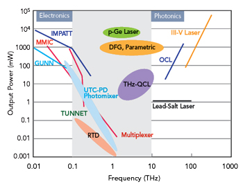
Figure 1 THz emission power as a function of frequency.2
6G mobile communications success will depend fundamentally on improved latency, higher data rates, better quality of service and expanded system capacity with THz waves central to realizing this ambition. With frequencies extending from 0.1 to 10 THz or wavelengths between 3 mm and 30 μm, THz occupies the spectral region between microwaves and optical waves. The prospect of large contiguous frequency bands providing extremely high data transfer rates in the Tbps range is making this a key research area for next-generation 6G wireless communications. Efforts to explore and unlock this frequency region require an interdisciplinary approach demanding close interaction between high frequency semiconductor technology for RF electronics and alternative approaches using photonic technologies. The THz region shows great promise for many application areas ranging from imaging to spectroscopy and sensing.1
There are multiple options for generating THz radiation. MMICs are an obvious candidate, but methods based on photonic technologies will also play a key role. The prospect of miniaturizing today’s lab setups into photonic ICs means these approaches could become mainstream. In communications, the frequency range of 100 to 500 GHz remains an untapped region, but research in this area is attracting increasing interest because these high carrier frequencies are associated with the promise of unprecedented channel capacities. The challenges and opportunities are making THz the final frontier in the electromagnetic spectrum.
CLOSING THE “THZ GAP”
Figure 1 shows the so-called “THz gap” in the frequency spectrum of 0.1 to 10 THz. This chart shows conventional THz sources with solid lines and recently developed THz sources with ovals. The chart shows a visible power drop in this region.
THz frequencies are too high for electronic devices because of excessive loss and limited carrier velocity. They are too low for photonic devices because of a lack of materials delivering a sufficiently small bandgap. Available power around the THz region is still much lower than in other spectral regions. A similar trend also occurs in signal detection where such a gap keeps this two-decade spectrum under-utilized in our spectrum-congested world.
There are three major approaches for generating THz radiation: classical electronics, direct THz generation with quantum cascade lasers and indirect generation optoelectronics. Figure 2 shows sources for THz radiation on the borderline between electronics and photonics.
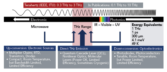
Figure 2 The three major approaches for THz radiation generation.
UP-CONVERSION: ELECTRONIC THZ GENERATION AND ANALYSIS
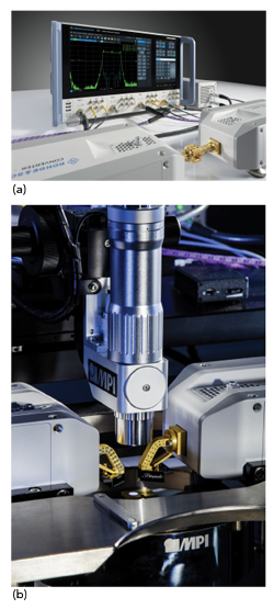
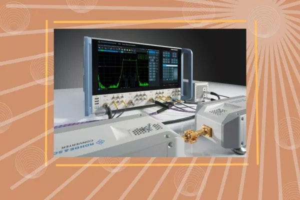
Figure 3 R&S ZNA vector network analyzer (a). R&S ZNA with MPI TS150-THZ integrated probe system for 330 GHz measurements (b).
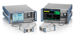
Figure 4 FE170ST and FE170SR D-Band signal generation and analysis test setup.
The “classic” approach has evolved tremendously. These components are very compact and can be operated at room temperature. The downside is that classical electronics cannot resolve bandwidth and efficiency limitations. Worse, electronic sources become inefficient at THz frequencies and provide only limited frequency tuning.
Fortunately, RF test and measurement equipment is available from vendors like Rohde & Schwarz to support 6G semiconductor, device and circuit characterization research in the mmWave and THz region. D-Band, with frequencies from 110 to 170 GHz, is seeing a strong research focus. Solutions supporting sub-THz and THz research include vector network analyzers (VNAs) for device characterization with frequency converters to 1.1 THz. External harmonic mixers extend frequency range support for signal and spectrum analyzers to D-Band and other frequency bands up to 500 GHz. Frequency multipliers extend signal generator frequency ranges to 170 GHz and beyond. Signal generation and analysis for the D-Band spectrum is possible with transmit (Tx) and receive (Rx) converters and antenna radiation performance measurements can be made using anechoic chambers. What follows investigates these test solutions in detail, outlining ways to generate and analyze THz waves for 6G research. We also describe the challenges presented by these bands.
VNA THZ MEASUREMENTS WITH METROLOGY-LEVEL ACCURACY
Measurements at frequencies up to 67 GHz are part of the standard repertoire of network analyzers. However, tests in the mmWave and THz ranges are significantly more demanding as they require external frequency converters. These frequency extenders up-convert stimulus signals and down-convert response signals to characterize devices operating at THz frequencies.
Characterizing active components in linear and nonlinear ranges requires a defined input power at the probe tip. Since on-wafer power calibration is not possible, the power at the waveguide output is calibrated by accounting for losses in additional waveguides, 1 mm cables and the probe tip. For power sweeps and compression point measurements, an integrated calibration routine in the R&S ZNA compensates for mmWave converter nonlinearities, providing maximum measurement dynamic range and reproducibility. The R&S ZNA uses system-integrated mmWave converters with metrology-level precision.3 This allows active component measurements to be as convenient at high frequencies as they are at lower frequencies. Figure 3a shows a representative test setup with the R&S ZNA. Figure 3b shows that test setup modified for 330 GHz wafer-level measurements.
WIDEBAND SIGNAL GENERATION AND ANALYSIS IN D-BAND
D-Band, with the prospect of several GHz of bandwidth, has become one of the focus frequency bands for 6G research. Figure 4 shows a typical signal generation and analysis setup supporting component and transceiver research in D-Band. The R&S FE170ST transmitter front-end up-converts the modulated signals from the R&S SMW200A vector signal generator to the 110 to 170 GHz frequency range. The R&S FE170SR receiver front-end down-converts the signals and transmits the intermediate frequency (IF) to the R&S FSW signal and spectrum analyzer.
ANTENNA RADIATION PERFORMANCE MEASUREMENTS IN D-BAND
5G pioneered the use of over-the-air (OTA) testing concepts for wireless communications in mmWave frequency bands. This was because large-scale and highly miniaturized antenna arrays are not easily accessible for conducted testing.4 OTA antenna test concepts can be extended into D-Band and beyond for exploring THz communications and sensing. Future devices will incorporate even more highly integrated active antenna systems for ultra-massive MIMO and sensing applications. With 6G research focusing on frequencies above 100 GHz, advances in new wideband high gain antenna concepts and applied antenna measurement procedures are needed.
Moving from legacy sub-6 GHz cellular services to 5G NR frequency range 2 (FR2) required a major technological leap. Since path loss increases with the square of frequency, higher gain antennas with electronic beam steering capabilities were introduced into user equipment and network infrastructure to ensure radio link performance. With the dramatic increase in IC complexity as a function of frequency, a majority of developments are now targeting a new incremental step at waveguide D-Band and G-Band (140 to 220 GHz). Rohde & Schwarz have developed a spherical scanning solution for measuring radiation performance in D-Band. The solution uses a new probe design with direct down-conversion that provides more than 50 dB dynamic range at 170 GHz. The R&S ATS1000 anechoic mobile spherical scanning range simplifies the test requirements because no mechanical modification or additional RF cabling is needed to measure the amplitude and phase-coherent response of a device under test (DUT) from 110 to 170 GHz.
EXAMPLE: OTA TESTING OF A D-BAND ANTENNA
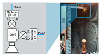
Figure 5 Block diagram and measurement setup of the spherical scanning system.
Figure 5 shows a newly designed IMST D-Band lens-based leaky-wave-fed antenna evaluated in a system using spherical near-field scanning. The radiation pattern measurements were carried out in the R&S ATS1000, which includes a distributed axis positioner. The DUT could be used in 6G fronthaul point-to-multipoint scenarios. The simplified feed structure consists of an elliptical lens made of low permittivity (εr = 2.34), low loss, high density polyethylene (HPDE) with 35 mm diameter (20 λ at 170 GHz). The feed consists of a λ/2 leaky wave air cavity, excited by a WR6 waveguide. The radiation pattern can be steered by displacing the feeder along the lens focal plane.