
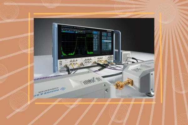
A DUT feeding assembly, shown below the lens antenna in Figure 5, is used to perform phase-coherent and time-stable measurements. This chain consists of a D-Band subharmonic mixer identical to the one used at the probe and a D-Band isolator that is attached to the WR6 split block of the DUT. Measurements are performed with the R&S ZNA43 four-port VNA where one port at the front feeds the IF signal to the DUT.
The block diagram in Figure 5 shows the measurement probe concept. An orthomode transducer is connected to a 20 dBi squared horn antenna with a 3 dB beamwidth of 16 degrees and a cross-polarization isolation of 25 dB over the complete D-Band frequency range. The assembly works reciprocally, transmitting or receiving two orthogonally-polarized fields when the DUT is set to Rx or Tx. Down-conversion or up-conversion occurs directly at the probe, removing RF cable loss. Both polarizations can be measured simultaneously.
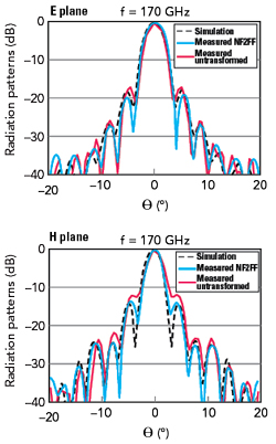
Figure 6 E-plane and H-plane directivity patterns.
The results in Figure 6 reveal excellent agreement between the DUT full-wave simulations and the measurements. This confirms the accuracy of the measurement system and technique involving the new probe design. Phase-coherent data acquisition such as near-field-to-far-field (NF2FF) transformation can be successfully realized for passive antenna measurements. The untransformed measurement results in red show that the main beam of the radiation pattern is already close to far-field asymptotic behavior.
The high efficiency D-Band lens antenna design realized gain greater than 30 dB over 42 percent bandwidth. Accurate characterization of this antenna was performed with a spherical scanning test system, capable of stable phase-coherent measurements, with direct frequency conversion at the DUT input and the test probe outputs. Phase coherence is a must to support the precise application of the near-field to far-field transformation algorithms that are essential for the accurate determination of radiation pattern nulls and sidelobe levels.
DIRECT THZ GENERATION WITH A QUANTUM CASCADE LASER
An alternative to electronic up-conversion is direct THz generation. This approach uses a quantum cascade laser (QCL) and nonlinear optics (parametric optical processes). Reasonable power levels can already be reached with a QCL, but efficiency remains limited and often they must operate at cryogenic temperatures.
To meet these challenges, down-conversion from the optical frequency regime using ultrafast photodiodes and photoconductors is another approach gaining interest. Down-conversion promises tunability over a broad range, operation at room temperature and the potential to reuse mature technologies developed for fiber-optic communications. The power envelope is being pushed, albeit with limitations in efficiency.
The generation of phase-coherent radiation in a laser is well-established and has led to applications combining optical communications with optical fiber technology. Central to success is allowing direct conversion of electrical current into coherent light. For optoelectronics, the direct bandgap III–V semiconductor materials GaAs and GaN are the most important.
Interband diode lasers are an inexpensive and efficient method for generating photons across the ultraviolet, visible light and IR frequency regions. However, THz photons have energies 100x to 1000x lower than visible photons and there are no materials with such a small bandgap and population inversion. To overcome these issues, laser emission is achieved in a QCL using inter-subband transitions in a periodic stack of semiconductor multiple-quantum-well heterostructures as depicted in Figure 7.
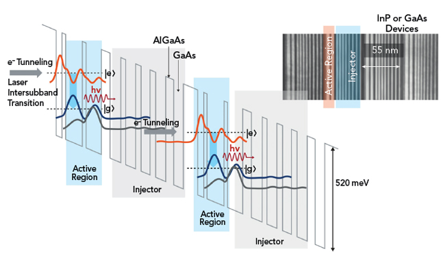
Figure 7 Lasing transition between inter-subbands engineered by semiconductor heterostructures in a QCL.
Well depths can be engineered by controlling the layer depths during the fabrication process. The wavelength of the lasing transition is dependent on the physical structure of the device. So-called “electron wavefunction engineering” allows the generation of low energy THz photons not accessible with interband diode lasers. Multiple photons can be generated by a single electron, making the process extremely efficient. Tunneling from one well to the next is where the term “quantum cascade” originates. Light is emitted as electrons that “cascade” through multiple quantum wells forming a superlattice.
Successful operation of a QCL at THz frequencies was first demonstrated in 2002.5 QCLs have quickly progressed in terms of frequency coverage, power output and operating temperature. By carefully designing the quantum wells, lasing has been achieved at wavelengths as short as 2.75 μm (109 THz) and as long as 161 μm (1.9 THz). Longer wavelength devices still require cryogenic cooling, but room temperature operation has been observed to at least 16 μm.
An approach using long wavelength THz QCL sources with intra-cavity nonlinear frequency mixing has made frequencies below 1 THz accessible. The journey towards a THz QCL that operates at room temperature has taken a step forward with the recent publication of a device that operates at -23°C. This temperature is within the reach of Peltier coolers.
DOWN-CONVERSION PHOTONIC APPROACH: FROM OPTICAL TO THZ VIA PHOTOMIXING
The third approach is optoelectronic frequency domain THz generation, which uses a uni-traveling carrier photodiode or PIN photodiode as a photomixer. This indirect approach for continuous-wave THz generation has attracted strong interest. A photodiode can efficiently convert an optical signal into an electrical signal via a process where optical/infrared laser light generates free charge carriers in a semiconductor or organic crystal. The antenna structure surrounding the photomixer translates oscillating photocurrent into a THz wave, as depicted in the photomixing process in Figure 8.
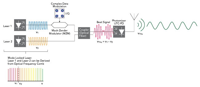
Figure 8 Photomixing process to generate THz radiation.
The photomixing process generates THz radiation at the beat frequency (νTHz = ν1 – ν2) of two slightly detuned single-mode lasers. One way to attain extreme frequency and phase stability is to derive both frequencies from an optical frequency comb. For data transmission, one of the lasers is modulated by a Mach-Zehnder modulator that consists of an interferometer that splits the beam into two arms. In one of the interferometer arms, the phase of the laser light is shifted relative to the other path by an electro-optic modulator resulting in a constructively or destructively modulated laser beam after the recombination of both beams. The beat signal impinges the photomixer uni-traveling carrier photodiode and the integrated antenna emits THz radiation.
State-of-the-art photomixers are based on either GaAs or InGaAs/InP and require laser wavelengths below the semiconductor bandgap (around 0.8 or 1.5 µm, respectively). By tuning the lasers, the beat note frequency can be varied over a broad spectral range, which translates directly into widely tunable THz radiation. This allows for use of the techniques developed to generate optical vector fields in optical communications, pushing these frequencies into the THz range. When adding frequencies, these techniques make it easier to implement multi-frequency communications. The combination also allows easy integration of these wireless links into fiber-optic infrastructure.
On-chip communications and future high speed inter-device communications will also require THz waveguides. These can be accomplished with topological valley photonic crystals exhibiting near-zero bending loss and zero back-scattering. Referencing both frequencies to the same frequency comb generator allows the transfer of the unique phase and frequency stability of optical combs in a broadband and tunable manner into the THz range. The receiver could be a Schottky diode or a setup symmetrical to the transmitter. This also holds promise for test and measurement instrumentation, since it can be scaled up to extend into the THz region range.
THZ WAVES FOR COMMUNICATIONS: 300 GHZ POINT-TO-POINT TRANSMISSION
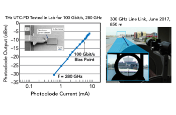
Figure 9 300 GHz data transmission in the lab (left) and an outdoor trial (right) (courtesy of Prof. G. Ducournau, IEMN, CNRS-Université de Lille).
THz data transmission trials with one Tx antenna and one Rx antenna have been performed in the lab and outdoors. Between 200 and 300 GHz, there is a transmission window with low atmospheric losses. In contrast to free-space optical links, mmWave or THz transmission is much less affected by adverse weather conditions such as rain and fog.
Figure 9 shows the successful trial results from the harbor of Dunkerque. This trial involved a 300 GHz, 850 m transmission link with an extremely focused beam. The responsivity of the device can be increased further with a metallic mirror below the diode mesa through wafer bonding. Further tests of 100 Gbps transmission in the terahertz window between 200 and 300 GHz have been demonstrated successfully.6
CONCLUSION
Continuous innovation in the field of test and measurement is a key enabler for making future 6G a reality. It will require intensive research in academia as well as innovative development in the industry. This research will continue to assist in the design of THz test and measurement products to provide solutions and expertise to pave the way for 6G, the next wireless communications standard.
References
- “Fundamentals of THz Technology for 6G,” Rohde & Schwarz, White Paper, September 2022 (Version 1.02).
- M. Tonouchi, “Cutting-edge Terahertz Technology,” Nature Photonics, Vol. 1, February 2007, p. 97–105.
- A. Rumiantsev, T. Naing Swe and A. Henkel, “Achieving Metrology-Level Accuracy When Making THz Measurements,” Microwave Journal, Vol. 59, Ed. 9, September 2016.
- R. Stuhlfauth and H. Mellein, “Over-the-air RF Conformance Measurements on 5G NR Devices,” Rohde & Schwarz, White Paper, 2021.
- R. Köhler, A. Tredicucci and F. Beltram et al., “Terahertz Semiconductor-heterostructure Laser,” Nature, Vol. 417, 2002, pp. 156–159.
- V. K. Chinni et al., “Single-channel 100 Gbit/s Transmission using III–V UTC-PDs for Future IEEE 802.15.3d Wireless Links in the 300 GHz Band,” Electronics Letters, Vol. 54, 2018, pp. 638–640.