
An RF identification (RFID) coding approach is based on the radar cross section (RCS) of a multi-patch chipless RFID tag. Combined with classical frequency coding, this increases the coding capacity. This work describes a six-resonator RFID tag using microstrip patches that has a high data capacity and low-cost. It can be directly printed on products such as personal IDs, credit cards, paper and textiles because it needs only one conductive layer. It is designed to operate over the range of 4.5 to 6.2 GHz, at frequencies allocated for RFID systems.
For several years, RFID technology has brought many innovations in the field of automatic identification of people and goods; however, for consumer product identification the barcode is still dominant.1 An RFID system consists of RFID tags and an RFID reader.2,3 RFID tags are attached to objects to be identified. Each RFID tag contains a unique tag identification number (tag-ID). The RFID tag contains electronic circuitry that stores the tag-ID and communicates wirelessly with the RFID reader. The RFID reader transmits an interrogation signal, which communicates with the RFID tag to obtain its unique tag-ID. The tag either actively transmits an RF response signal or passively reflects (backscatters) the interrogation signal. The tag response is captured by the RFID reader antenna and processed by the reader to extract its tag-ID.4-7
Chipless technology is of interest since its cost is lower than technologies with active chips and it enables operation under adverse environmental conditions where electronic chips can be easily destroyed. There has been much research focused on high performance chipless RFID tags.8,9 Numerous resonant topologies have been proposed, such as U-shape,10 L-shape,11 octagonal,12 slot,13 triangular patch,14 microstrip line15 and shorted dipoles oriented at 45 degrees.16
According to the encoding method, chipless RFID tags can be grouped into two main categories: 1) frequency signature based17-20 and 2) time domain reflectometry based chipless RFID.7,21-23
Recent development in the era of low-cost and compact communication systems has largely been due to the advent of small weight and size antennas that can provide good performance over a broad frequency range. The rectangular microstrip patch is an attractive choice. Its theory of operation is computationally simple. It is low-cost, easy to fabricate and is conformable. It enables low-profile structures of compact size that assure reliability, mobility and good efficiency.
This work describes a chipless tag comprising six patch resonators with coding based on control of its RCS magnitude over a 1.6 GHz bandwidth from 4.5 to 6.2 GHz. The effects of mutual coupling are also explored. Phase, along with frequency coding, enables increased coding capacity. Measurements validate simulation.
MICROSTRIP PATCH RESONATOR DESIGN
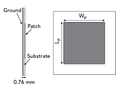
Figure 1 Microstrip patch antenna geometry.
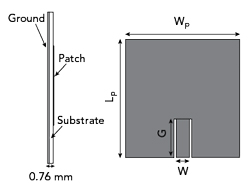
Figure 2 Geometry of the chipless RFID tag using slots to reduce size. Lp = Wp = 16.5, W = 1.2 and G = 6 mm for a patch resonant at 4.6 GHz.
The microstrip patch is designed to operate over a narrow band. In the design of RCS magnitude-based chipless tags, resonant behavior is desirable. The design procedure is described by Karmakar.24 It is fabricated on a 0.76 mm thick Rogers RO4350B substrate (see Figure 1).
The width Wp and length Lp are given by the following equations:25

where
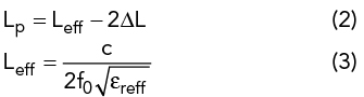
And ΔL is determined by

Where c is the speed of light in a vacuum, h is the substrate thickness and εreff is the effective permittivity given by the equation:

PARAMETRIC STUDY
The microstrip antenna’s patch length Lp and width Wp are calculated theoretically to be 17.2 and 21.7 mm, respectively, for resonance at 4.6 GHz, the target frequency of the lowest frequency patch. A parametric study of the dimensions of the patch antenna with slots (see Figure 2) is done to optimize performance and reduce size (Lp = Wp = 16.5 mm).

Figure 3 RCS magnitude over frequency vs. Lp and Wp (a) and W vs. G (b).
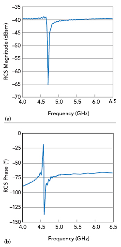
Figure 4 RCS magnitude (a) and phase (b) of the optimized 4.6 GHz design.
The parameter sweep section of the CST Studio Suite is used to optimize the various patch parameters. Changes to Wp, Lp and slot dimensions W and G have a significant impact on RCS. Figure 3a shows the resonant frequency as a function of Lp and Wp. The initial result, using dimensions analytically derived show resonance at f = 3.6 GHz. After optimization, resonance is achieved at f = 4.6 GHz with Lp and Wp both equal to 16.5 mm. For best results, W = 0.9 to 1.5 mm and G = 4 to 8 mm, as shown in Figure 3b. Figure 4 shows the final magnitude and phase response of the 4.6 GHz patch.