A wideband microstrip patch antenna having a hexagonal radiating patch with linear and circular polarization is proposed for multiband applications. The radiating patch is perturbed with three slits and is shorted to ground using a copper pin. The perturbation of the radiating patch with three optimum slits enhances the impedance bandwidth. Shorting of the patch to the ground plane changes a portion of the radiated frequency band from linear to circular polarization. The unique feature of the antenna is that it exhibits both linearly polarized and circularly polarized properties in a single structure. It can be used for transmission and reception of differently polarized signals simultaneously. The probe-fed antenna has an impedance bandwidth of 1.29 GHz, 42.4 percent, from 2.4 to 3.69 GHz for |S11| ≤ -10 dB. It has a broadside radiation pattern with a gain of 3.7 dBi at 2.5 GHz and 5.9 dBi at 3.68 GHz.
The antenna is the heart of all wireless communication equipment and plays an important role in determining the quality of radio communication. Present and future advanced wireless communication systems require antennas to have wide bandwidths to support higher data rates and capable of operating over the multiple frequency bands defined by various protocols. More than one antenna is often required to support different frequency bands and polarizations, leading to an increase in the space required for the antenna, while the available space keeps decreasing.
A conventional microstrip patch antenna transmits linearly polarized radiation over a relatively narrow band. Many advanced wireless communication systems, however, require wide bandwidths to support high speed data communication and multiple application bands. If a microstrip patch antenna is to be used in these applications, it must be modified to provide the wide bandwidths required, as well as having the ability to radiate circularly polarized waveforms.
Much has been reported on bandwidth enhancement techniques, including: 1) slotting or slitting of the radiating patch,1-4 2) thicker substrates with a low dielectric constant,5 3) stacking of patches,6 4) addition of parasitic patches with a main radiating patch,7 5) aperture coupling8-10 and 6) proximity couple feeding.11-14
An antenna radiates a signal with circular polarization when it generates two orthogonal modes with the same amplitude and 90-degree phase difference between them. Some of the techniques which have been used to enhance bandwidth can also be used to change the polarization of the antenna, such as perturbation of the radiating patch with slits or slots,15-17 attaching a stub18 and stacking of patches.19 Other techniques include perturbing the patch with spur lines20 and overlapping patches.21
The antenna described here is a wideband microstrip patch antenna that works as a linearly polarized antenna for some portion of the resonant band and a circularly polarized antenna for another portion of the band. The radiating patch is hexagonal with three slits. The patch is shorted to the ground plane using a copper pin, which causes some portion of the linearly polarized band to be converted to circular polarization. The low profile antenna exhibits an impedance bandwidth of 1.29 GHz (42.4 percent), which spans multiple application bands.
ANTENNA DESIGN
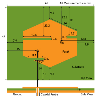
Figure 1 Top and cross-section views of the antenna design. Dimensions in mm.
The complete size of the antenna is 47 × 40 × 6 mm3 (see Figure 1). The patch is perturbed with three slits, and the patch and ground plane are shorted using a copper pin with a 0.63 mm radius and 6 mm height. The radiating patch is a thin copper sheet on 6 mm FR4 material with εr = 4.4 and tanδ = 0.02. A 50 Ω coaxial probe with an SMA connector situated 15 mm from the left edge and 19 mm from the bottom edge of the substrate is used to excite the antenna.
Initial Design and Parametric Study
In a microstrip patch antenna, size determines its primary resonant frequency. There is close similarity between hexagonal and circular patch antennas; therefore, Equation 1, which is used for calculating the resonant frequency of a circular patch antenna, and Equations (2) and (3) are used to calculate the primary resonant frequency of the hexagonal patch antenna.22

where fr is the resonant frequency of the circular patch antenna, Xmn = 1.8411 for the dominant TM11 mode, c is the speed of light in free space, εr is the relative permittivity of the substrate and ae is the effective radius of the circular patch.
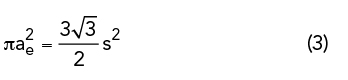
where s is the side length of the regular hexagonal patch.
After parametric calculation with different side lengths, 14 mm was chosen to provide a primary resonant frequency of 3.11 GHz, close to the desired result. After theoretically calculating the resonant frequency of the hexagonal microstrip patch antenna, HFSS version 13 software was used for the initial design and analysis. The optimum probe location was found by placing the probe at different positions on the patch and analyzing the results. At the optimum probe location, 15 mm from the left edge and 19 mm from the bottom edge of the substrate, the primary resonant bandwidth is 390 MHz (2.83 to 3.22 GHz) for |S11| ≤ -10 dB (see Figure 2).
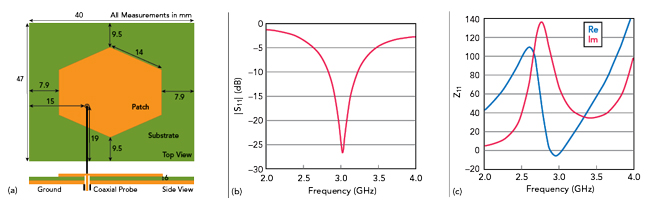
Figure 2 Initial design: optimum probe position (a), simulated |S11| (b) and simulated Z11 (c).
Effect of First and Second Slits
Perturbation of the radiating patch with slits adds capacitive reactance and lengthens the surface current path. This added capacitive reactance causes an LC resonance with the stray patch inductance creating an additional resonant frequency band. When the additional resonant band is close to the primary resonant band, the overall bandwidth of the antenna is increased. The lengthening of the surface current path causes a shift of the frequency band toward the lower side of the frequency range.23-27
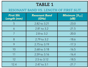
The first slit was initially chosen to be 1 mm wide and 5 mm long. Analysis showed little shift of the resonant frequency toward the lower side of the frequency range and improvement in S11. A parametric simulation using HFSS was done with a 0.4 mm width and various slit lengths. Observing |S11| and the input impedances, a 0.4 mm width and 12.4 mm length provide the best performance; changing the length and width beyond these dimensions provides unwanted results (see Figure 3 and Table 1).
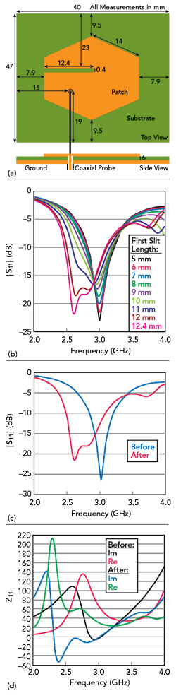
Figure 3 Initial design with optimum probe position and first slit (a), variation of the resonant frequency bandwidth vs. first slit lengths and width = 0.4 mm (b), |S11| before and after first slit length optimization (c) and |Z11| before and after first slit length optimization (d).
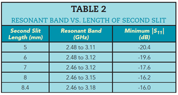
To further improve bandwidth, the hexagonal patch was perturbed with a second slit, keeping the probe position and first slit unchanged. The same optimization process was used. After perturbation with the optimized second slit, the antenna bandwidth was further improved (see Figure 4 and Table 2).

Figure 4 Design incorporating second slit (a), variation of the resonant frequency bandwidth vs. second slit lengths and width = 0.6 mm (b), |S11| before and after second slit length optimization (c) and |Z11| before and after second slit length optimization (d).