
A mmWave power booster enables increased output power by more than 10 dB without appreciably deteriorating signal integrity. It enables high-power 71 to 86 GHz communications up to 10 Gbps in a 2 GHz channel and paves the way for commercial mmWave links up to 5x current link lengths at E-Band.
As mobile communications evolve into their fifth generation, the offer of higher data speed and reduced latency puts a strain on the radio access sites and on the whole network, including its transport segment.1 For wireless backhauling connections, as well as fronthauling and midhauling links as envisaged by the open-RAN paradigm,2 this entails capacities larger than 10 Gbps and advanced fast processing capabilities.
To deal with similar needs, existing spectrum regulations traditionally offer channels in the microwave range (6 to 42 GHz), but these are too narrow to support more than 1 Gbps in each; while 2 GHz channels are available in the mmWave domain, specifically in the commercial E-Band (71 to 86 GHz) where a 128-QAM modulation can easily sustain 10 Gbps. Network operators are thus planning and deploying equipment for E-Band communications, and equipment manufacturers spend substantial effort in researching and developing such products.
The shift to E-Band, however, comes with some steep costs: 1) difficulty to obtain high power from available components, 2) larger propagation attenuation and 3) higher sensitivity to precipitation (i.e. rain, hail and snow). All of these concur to limit the achievable link distance, hence the modern wireless tradeoff of capacity versus distance.
While the latter two costs express physical phenomena, the former represents a technological limitation, which can be tackled. Part of the answer is provided by the use of large, more directive antennas, in turn requiring precise compensation of misalignments.3 Instead, this paper outlines a complementary answer: a novel E-Band power booster to enable high capacity backhauling, fronthauling or midhauling in the mmWave region, which has been developed and tested in the field.
POWER BOOSTER ARCHITECTURE
The typical architecture of commercial backhauling equipment is based on a digital modem, some analog baseband or intermediate frequency circuitry and up-conversion to 71 to 86 GHz followed by a power amplifier (PA). Current commercial equipment dedicated to E-Band backhauling offers a transmitted power between 10 and 20 dBm at the various modulations.

Figure 1 Current single PA architecture with gain G (a) and parallel architecture with N identical PAs fed by a driver power amplifier (b).
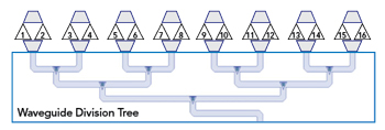
Figure 2 16-way binary division with one to eight splits in waveguide, the last using an alumina splitters.
Increasing the output power through the same components would cause severe distortion of the transmitted signal. Regardless of the traveled distance, it would reach the receiver with excessive distortion for error-free communication even after standard forward error-correcting schemes are applied.
Integrated PAs can leverage different semiconductors, chiefly GaAs, SiGe and GaN. Most of today’s RF circuitry is GaAs based. Cost and power-handling capabilities, however, are directly related when switching to low-power cheap (in volume) SiGe and high power, but expensive, GaN. A reasonable tradeoff can instead be realized with an architectural change, by employing parallelization, while still using GaAs components.
As shown in Figure 1, a driver amplifier provides, via an ideal division network, the same input power to each of the N PAs as in the single amplifier case. In the simple third order model of non-linearity, each amplifier produces a distortion component proportional to the cube of the input power. After proper in-phase recombination, the same signal-to-distortion ratio is obtained as with the single amplifier but with a much higher level of transmitted power; 10log10(N) = 12 dB is the theoretical output power increase achievable with this architecture when N=16 identical parallel PAs are used.
COMPONENTS
For a paralleled architecture to be of practical interest, the division and recombination network must avoid power loss along the path. To this purpose, the structure shown in Figure 2 includes a one to eight waveguide binary tree,4 providing low loss due to the fine surface finish of the inner metal walls. The binary tree guarantees uniformity in amplitude and phase. To minimize reflections at the interfaces and maintain isolation between the connected amplifiers, the basic node is designed as a so-called “magic tee.”5 The final further division by 2 is implemented in planar technology on alumina. The same binary tree is mirrored to serve as recombination network.
The waveguide networks are machined in two aluminum lids in which the waveguide trees and the internal loads are milled (see Figure 3). The lids close as a sandwich to the inner aluminum body, which feature small pyramids to minimize impedance mismatches and seal the carved waveguide paths. The common input and output ports, in WR12, are located on the bottom side, where the 8+8 ports toward the amplification chains are visible on the top. Each tree exhibits a net 0.7 dB loss (beyond the theoretical 9 dB) and a total phase imbalance less than 15 degrees between all ports.
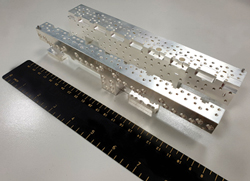
Figure 3 Waveguide divider network shown at the top right, with the lid detached from body. The recombination network shown at the bottom left, with the lid and body assembled.

Figure 4 PA structure, including the WR12 waveguide launchers, alumina splitters and PA die.
The 3 dB alumina splitters used as the topmost stages introduce a further 0.5 dB of loss each along with the various bonded interconnections shown in Figure 4. All chains are fed with good in-phase and equal-amplitude signals and their recombination follows the same rule; considering recombination losses, an expected practical increase of output power of +10 dB with respect to the single amplifier case is the expected outcome.
LABORATORY VALIDATION
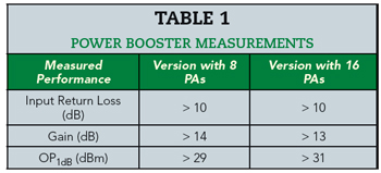
The entire power booster is assembled in a first version with eight PAs without the alumina splitters, and then later in its full-fledged version with 16 PAs. Table 1 summarizes the results from a 2-port characterization between 71 and 86 GHz.
These measurements show an increased variability versus frequency in the performance of the 16-PA version, due to the alumina splitting stage and the additional manual bonding introducing further uncertainty. The 16-PA version, however, exhibits an output power at 1 dB of compression (OP1dB) that is as much as 3 dB higher than the 8-PA version, thus enabling higher sustained output power.