
The power booster is tested on actual modulated signals to assess whether the currently required signal-to-distortion ratio (S/D) is achievable at a +10 dBm output power level with respect to a state-of-the-art commercial unit based on a single PA (ALFOplus80HDX by SIAE MICROELETTRONICA). The ALFOplus80HDX full-outdoor unit is capable of 20 dBm in 4-QAM (2 Gbps throughput over 2 GHz bandwidth) and 13 dBm in 128- and 256-QAM (up to 10 Gbps), with a guaranteed overall S/D at the receiver of 29.5 dB in nominal conditions of received power and with a factory-calibrated transmitter.
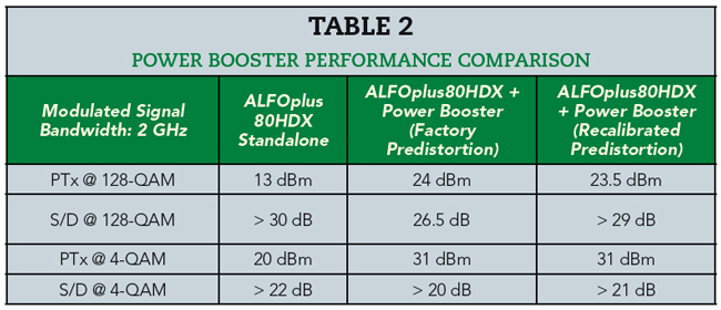
By adding the power booster to an ALFOplus80HDX configured as transmitter-only and using a power meter and another ALFOplus80HDX as a receiving terminal, the performance summarized in Table 2 is measured. The columns compare the transmitted power (PTx) and S/D ratio (as reported by the receiving equipment), which measures the quality of the received signal at a prescribed received power (dominated by distortion from the transmitter) in three configurations:
1. A standard ALFOplus80HDX equipment (without any power booster)
2. An ALFOplus80HDX with power booster but without any specific recalibration of predistortion coefficients
3. The same equipment with the power booster after recalibrating the predistortion coefficients of the transmitter.
Predistortion is a numerical process which allows compensation of nonlinearities introduced by the analog stages and should thus be fine-tuned for a specific transmitting chain, which justifies the large improvement of signal-to-noise ratio after recalibration. The results show that the power booster enables increased output power by more than 10 dB without appreciably deteriorating signal integrity after recalibration of the transmitter predistortion. It enables high-power 71 to 86 GHz communications up to 10 Gbps in a 2 GHz channel.
FIELD TRIAL
In the wake of successful laboratory tests, a field trial in cooperation with Deutsche Telekom/COSMOTE Greece uses an outdoor booster connected to existing ALFOplus80HDX equipment. However, since the booster acts only in transmission, while the equipment uses frequency-division duplexing to transmit and receive simultaneously through the same physical antenna port, the prototype includes:
1. A duplexer (to separate transmitted and received bands from the equipment)
2. The power booster on the transmit path
3. A straight waveguide on the receive path
4. Another duplexer (to expose a unique antenna port).
This waveguide structure, required only for the field prototype, is enclosed in a metal container providing heat sinks and mechanical interfaces with the equipment and the 60 cm antenna.
To compare in real time the advantages of the power booster, only one end of the trial link is equipped with the booster prototype, whereas the other end includes only an ALFOplus80HDX and a 60 cm parabolic antenna (see Figure 5). The direction from the terminal with the power booster transmits at 74 GHz, where the direction from the terminal without the booster transmits at 84 GHz, both over 2 GHz channels.
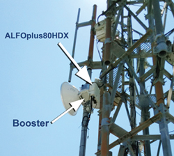
Figure 5 Athens link with power booster.
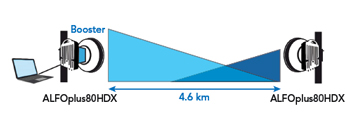
Figure 6 Athens field trial using a site equipped with the power booster (left), transmitting at 74 GHz and receiving at 84 GHz, and a site without the booster (right), transmitting at 84 GHz and receiving at 74 GHz.
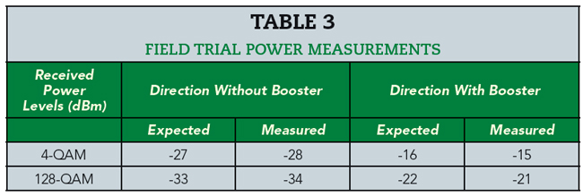
Two suitable line-of-sight sites in the Athens region were identified with a separation of 4.6 km (see Figure 6). Monitoring equipment was also installed to record received power levels and modulation in both directions by querying the local and remote equipment every 2 seconds. After aligning the antennas on a clear day, received measured power levels are shown in Table 3. The values highlight an improvement of more than 10 dB in received power because of the power booster. This considers the accuracy of the internal power meter of about ±1 dB and the inherent differences between the two directions due to the slightly different transmit frequencies.
Both ends were configured to use automatic modulation, so that the two ends automatically maintain the highest modulation compatible with error-free communication in the instantaneous link conditions (i.e. rain fading). Both equipment switched automatically to the maximum capacity of 10 Gbps.
Over the monitoring period, the link transported more than 2,000 Pbit (1 Pbit = 1015 bit) in each direction, as the maximum 10 Gbps (128-QAM modulation) could be maintained for the vast majority of time, where rain events occurred only in a few days. A sample of the monitored received power and modulation is shown in Figure 7.
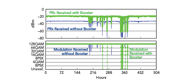
Figure 7 Received power and modulation vs. time. The green traces show the power and modulation received from the transmitter with the power booster; the blue traces show the power and modulation received from the transmitter without the booster.
An exceptional rain event with torrential precipitations in the Athens area was recorded, with rain intensity greater than 100 mm/h, causing numerous power outages and unreachability of the network elements. Several tens of minutes of unavailability were gathered in both directions during this severe thunderstorm. Discarding this data, the rest of several seasons included light as well as medium rain events, obtaining the aggregated performance in Table 4.
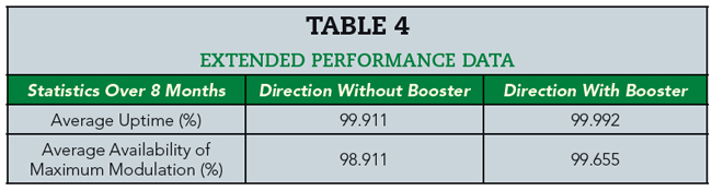
The direction that leverages the power booster reduced downtime by 91 percent and the non-maximum modulation (corresponding to less than 10 Gbps per direction) time by 70 percent with respect to the same link without the booster in transmission.
CONCLUSION
The modern needs for very-high capacity demanded by modern 5G networks is hampered by physical and technological constraints that limit the reachable hop length in wireless mmWave transport. The adoption of a parallelized PA architecture, however, circumvents some of the hurdles and so enables long-reach connections in the commercial E-Band.
The power booster prototype relies on a one-to-eight waveguide distribution and recombination structure feeding double PAs that yields a 10 dB increase in transmitted power. A 4.6 km field trial monitored through a multi-seasonal period validates the approach, thus paving the way for commercial mmWave links up to 5x current link lengths at E-Band.
Future activities will be dedicated to integrating the power booster in next-generation wireless transport equipment and industrializing the product, while also investigating alternative technologies such as GaN.
References
- A. Nordrum and K. Clark, “5G Bytes: Millimeter Waves Explained,” IEEE Spectrum, May 2017. Web. https://spectrum.ieee.org/video/telecom/wireless/5g-bytes-millimeter-waves-explained.
- “O-RAN Architecture Overview,” O-RAN Alliance, Web. https://docs.o-ran-sc.org/en/latest/architecture/architecture.html.
- M. Oldoni, S. Moscato, G. Biscevic and G. Solazzi “A Steering Antenna for Long-Reach mmWave X-Haul Links,” Microwave Journal, Vol. 21, No. 10, October 2021.
- S. Moscato, M. Oldoni, G. Cannone, D. Tresoldi, A. Pini and A. Colzani “8-way Paralleled Power Amplifier for mm-Wave 5G Backhauling Networks,” European Conference on Antennas and Propagation, March 2021.
- “TEE Junction | E-Plane Tee, H-plane Tee, Magic Tee,” Electronics Club, Web. https://electronics-club.com/tee-junction-e-plane-tee-h-plane-tee-magic-tee.