

A smart repeater deployed between the gNB and the UE, which is close to materials that actively reduce signal propagation, can ensure stable results where high transmission loss is an issue. Figure 6 shows the results for the deployment scenario shown in Figure 2, with and without a repeater.
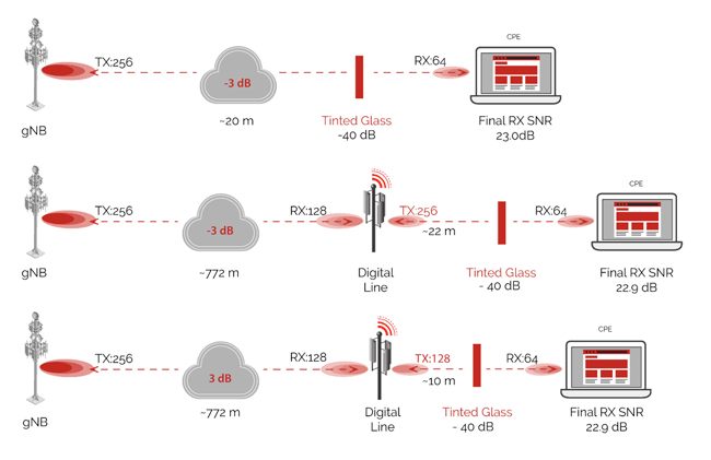
Figure 6 Using a repeater to address high transmission loss.
ACTIVE REPEATER DEPLOYMENT SCENARIOS
By enabling multiple-access options via time slots, frequency and physical space or range, a single active repeater can support several types of UE scenarios:
Static Single Beam
The repeater receives a single stream covering the full frequency channel and retransmits it fully over a single narrow beam, where the beam is expected and known to cover all UE.
Switching Multi-Beam
The beam setting of the repeater is switched on a time slot basis. The repeater receives a single stream covering the full frequency channel; it retransmits the stream fully by switching beams, where the beam profile during each time slot is associated with the sole UE assigned to that time slot.
Concurrent Multi-Beam
The repeater can be configured to concurrently retransmit the full bandwidth mmWave signal over multiple beams covering all UE.
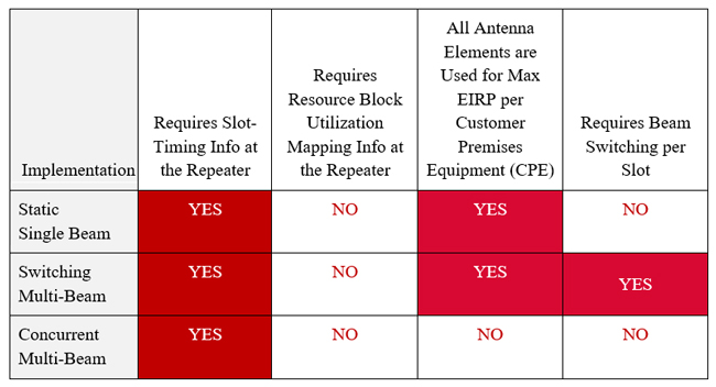
Table 1 summarizes the key characteristics of the multiple-access variations. A smart active repeater can be designed to dynamically support all three types of beams by reconfiguring the beamforming resources within the repeater. Beam reconfiguration can be applied during installation or operation. Given the reconfigurable and dynamic nature of this multiple-access architecture, a single repeater can support several types of UE.
TABLE 1 - REPEATER REQUIREMENTS FOR MULTIPLE-ACCESS SCENARIOS
Multi-Hop No-Latency Repeaters
Figure 7 shows a deployment scenario where four hops are configured between the gNB and the last repeater in the chain. The hops extend the range between the gNB and the last repeater to more than 2 km with nearly zero latency over the hops, since each node does not perform de-modulation/remodulation. Analysis of the gradual degradation of the error vector magnitude (EVM) as the signal propagates through the repeaters shows that a target signal-to-noise ratio (SNR) of ∼23 dB is still maintained at the very last repeater node.
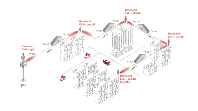
Figure 7 A nearly zero latency multi-hop repeater scenario.
The complexity of beam search and refinement at the repeater can be handled by the management software, which is responsible for establishing the mesh links between repeaters, a technique called software-defined beam networking.
The management software is also responsible for optimizing the relay radiation pattern to maximize the capacity and performance of the UE. It actively monitors the communication link quality, mitigates interference and follows dynamic changes in the communication channel, applying machine learning to model the behavior and control the mesh.
In the case of beam mesh networking, the repeater must follow the system timing to avoid creating interference between mesh nodes, as well as the gNBs. To prevent the increase of a noise floor for gNB reception, it is better to use a network of repeaters in a mesh configuration to minimize the direct connection of the repeaters to gNBs. This is even more important for private networks, especially for indoor applications with many reflections from walls and objects back to the repeaters.
USING RSSI/TSSI MEASUREMENT IN REPEATER EQUIPMENT
Transmit signal strength indicators (TSSI) and received signal strength indicators (RSSI) can be used by the repeaters to improve both uplink and downlink connections.
TSSI measurements may be performed by coupling the output of the last stage power amplifier in transmitter chains. TSSI is primarily used to help calibrate the absolute transmitter power levels and help transmit power control (TPC) flows.
RSSI is a measurement of the power present in a received radio signal. RSSI measurements have two purposes: 1) used to configure the optimal gain distribution within receiver chains and 2) part of the TPC flow to adjust the transmit power of cascading transmitter chains. RSSI may be measured in the analog or digital domains, determined by the type of implementation. With the availability of a digitized signal in the smart repeater implementation, highly accurate RSSI measurements can be achieved by suppressing adjacent channel signals.
Another use of RSSI is to adjust the relative power of signals corresponding to the different UE in the uplink. Multiple-access based on orthogonal frequency-division multiple-access (OFDMA) in the uplink requires careful control of the relative power of the signals associated with different UE to ensure a user’s adjacent leakage does not degrade the neighboring users within the same channel.
This is critical in the case of “concurrent multi-beam” implementation during uplink slots, where the different CPE signals are received in uplink time slots through different beam patterns and distances. The repeater superimposes these signals and transports them as an uplink to the gNB as a single stream occupying the full channel. To improve and speed up the relative TPC procedure in the uplink, the repeater may use the RSSI measurements of the signals received from different UE to equalize for gain differences (e.g., due to differences in distances and beam gains) before superimposing the signals and transporting them to the gNB.
CONCLUSION
By holistically tailoring the 5G radio and beamforming antenna as a complete system, the performance issues of mmWave communications systems can largely be solved. Mobile technology providers are responding to this by delivering mmWave RF front-ends, large phased-array antenna designs and smart active repeaters that enable high performance, broad coverage and high availability users expect from 5G networks. These innovations will enable network and service providers to launch enhanced indoor, outdoor and mobile services capitalizing on the advantages of mmWave technology.