
MODEL-BASED SYSTEM ENGINEERING
The preferred method of system architects now is to anticipate, as early as possible, the impact of each technological choice on the entire chain, even before the production phase, to avoid any pitfalls. Recently, manufacturers have been leaning toward a design methodology called “Model-Based System Engineering (MBSE).”1 The approach consists of including models to support the tasks of the definition of specifications, design, analysis, verification and validation of the system at all stages of development.
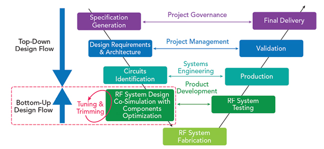
Figure 4 V-Model design cycle based on a Model-Based Design approach.
Precise models for each element of the chain are then necessary. As illustrated in Figure 4, the iterative loops for refining the specifications are conducted only during the simulation and are no longer in the post-manufacturing stages. In this case, total confidence is placed in the accuracy of the circuit models in the system simulation. It then makes it possible to implement a genuine bottom-up design flow methodology, consisting of checking the overall specifications of the system before production.
The top-down design methodology has largely proven itself in designing ICs for the digital part of systems.2 This approach makes it possible to conduct the synthesis of the circuit from the specifications. It integrates a bottom-up verification phase through dataflow simulations in the time domain (timed dataflow). These simulation techniques have proven effective due to their speed and reliability, thanks to the high level of abstraction of the digital blocks by a high-level description language.
Similar approaches are desirable for the analog part of the system, but considering critical effects coming from the RF/microwave circuits in this type of simulation is more problematic. Taking into account behaviors such as non-linearity, memory effects and mismatches, are essential for verifications at the system level. Unfortunately, circuit-type simulations have proven to be unsuitable at this high level of abstraction because of the significant computational effort and the resulting long simulation times to process wideband modulated signals.
To enable accurate and fast system simulations, a reliable behavioral modeling solution for each RF circuit is necessary to simplify each circuit’s description without losing quality concerning the knowledge of the behavior of each block. This uses mathematical equations describing the relationships between each circuit’s input and output ports.
These equations are used for accurately reproducing the behavior of the observed circuit, either from measurements obtained on a test bench or from more physical circuit simulations, where each elementary component constituting the circuit itself makes the object of precise modeling beforehand.
In recent years, many efforts have been made on this topic that we describe here. This article is mainly interested in PA behavioral modeling for system simulation, which is critical in analyzing and optimizing communication systems.
RFPA BEHAVIORAL MODELING
Various specialized commercial software allows the communication system’s architecture design to evaluate the performance in terms of bit error rate throughout a transmission chain. These simulators are a timed dataflow type and allow the efficient simulation of information encoded in the form of a digital signal in the time domain. However, the simulation can only be realistic if it considers the degradation caused by the analog front-end blocks, particularly by the PAs.
Unfortunately, designers face a lack of effective methodology to properly model PAs at the system level, either from measured or simulated data at the scale of each circuit. Although circuit-type models make it possible to obtain realistic behaviors on relatively simple signals (CW, two-tones) thanks to analysis techniques in the frequency domain (Harmonic Balance Method), the problem is too big to be solved in the time domain, especially with the Envelop Transient (ET) method, resulting in prohibitive simulation times. Simulation convergence problems can also be observed. Means of characterization in measurement now make it possible to know the real performance against application signals. On the other hand, the quantity of data quickly becomes important if one wishes to measure each variation of circuit parameters (load impedance, bias, temperature) and the signal (average power, peak-average ratio, bandwidth).
Currently, models proposed in these system simulators can accurately reproduce the circuit’s behavior only for stimulation conditions relatively close to those used to extract the model. For example, the Poly Harmonic Distortion Model,3 defined as a non-linear extension of the S-parameters. This model is treated in the system simulator as the static non-linear gain of the device. Even though this model proves to be relatively precise for simulating the circuit’s response when the latter is excited by a CW signal, it quickly exhibits significant inaccuracy when simulated with modulated signals.
Conversely, the Generalized Memory Polynomial Model4 makes it possible to faithfully reproduce the output of a circuit subjected to a modulated signal. Nevertheless, the extraction of the model is only possible from measurement data due to the limitations of circuit simulators (ET simulation) and the accuracy is guaranteed only for signals having the same characteristics as the identification signal (bandwidth, average power, frequency, PAPR).
Many models presented in the literature3 are based on variants of the Volterra series or Neural Networks. However, no implementation of these models is available in commercial simulators. Even when integrating custom models is possible, it requires specialized skills that only a few engineers master, creating a real risk for manufacturers in developing and maintaining these models.
Finally, manufacturers find themselves without an effective procedure to virtualize the behavior of their communication system realistically and benefit from all the advantages that the MBSE approach can bring for different use cases without the RF signal statistics being perfectly known in advance. Therefore, the solution to solve this challenge is to have available circuit behavioral models that are more general in terms of their use while limiting the complexity of the extraction procedure.
COMPREHENSIVE MODELING WORKFLOW
A comprehensive modeling workflow needs to offer a practical solution to extract, simulate and use these behavioral models in system simulators. An example of this is the VISION modeling tool. A key point offered by this procedure is to be able to extract a model from measurements or simulation results obtained at the circuit scale (see Figure 5). For example, a behavioral model of a linear circuit can be obtained by a simple S-parameters characterization using a VNA or a circuit simulation.
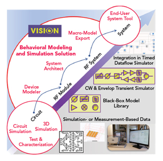
Figure 5 A comprehensive modeling workflow.
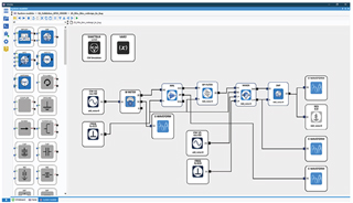
Figure 6 System simulation schematic.
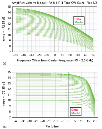
Figure 7 Power amplifier non-linearity modeling integrating the frequency dispersive aspects.
Since this frequency-domain characterization is not directly compatible with a dataflow type system simulator, a “Device Modeler” tool can automatically create a description function in the time domain, as shown in Figure 6. The user can apply this model directly in the “System Architect” environment using an “ET” simulation with broadband application signals and see the impact of the frequency dispersion of the circuit on the signal (ripple, roll-off, etc.).
Exporting the model to a system simulator allows the system engineer to obtain more realistic simulation results instead of using the circuit’s nominal gain or loss (S21) value. Also, the exported model integrates the solver, which calculates the implicit relations between voltage and current at each model port, thus making it bilateral. More precisely, the incident and reflected waves at each port are available at the system simulator level.
This method allows the global evaluation of a communication system, considering the impedance mismatch of the RF block in a system simulation environment. This methodology described for a linear circuit is completely transposable to modeling non-linear circuits such as PAs. The proposed solutions benefit from the work carried out from the continuous-time modeling theory,5 which manages large impedance mismatch and short-term memory (see Figure 7).
By completely designing the architecture of the RF front-end in the comprehensive modeling workflow simulator, the system engineer can benefit from the advanced models of each circuit composing the subsystem and from the simulator’s capabilities to predict the models’ interactions at each architecture node.