
These modeling and simulation capabilities pave the way to creating an RF front-end digital twin. This digital twin hosts an accurate representation of reality, which is used for the simulation, optimization and prediction phases at the system level. In addition, the representation stores and is fed by all the available data of each element during all the development phases of the system.
These possibilities have been echoed in several system-level applications. Now an example is presented as a hot topic for system designers: the accurate simulation of the RF front-end architecture of an active antenna. With this type of analysis, the designer tries to understand the impact on the system in the absence of a circulator in the architecture. Removing the circulator reduces the cost and size of the design. On the other hand, the interaction between the antenna and the front-end creates new interference to the PA, affecting the system’s overall performance.
ACTIVE ANTENNA’S FRONTEND SIMULATION
The simulation of a front-end architecture is proposed here to show the benefit of using advanced behavioral models. The front-end module comprises a variable attenuator (DSA) and phase shifter (DPS) to achieve the desired beam’s steering. The PAs are located after these devices and connected directly to the ports of the antenna, as shown in Figure 8.
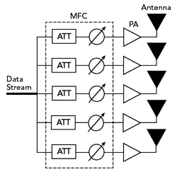
Figure 8 Front-end architecture schematic.
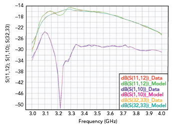
Figure 9 Subset of antenna S-parameters.
The antenna6 contains 36 radiating elements and is characterized by an S-parameters matrix. Similarly, the DSA circuits and the DPS have been characterized with S-parameters for different digital control states. This module is controlled by two digital ports with seven and eight bits, representing 32,768 states. Each of them is characterized by S-parameters. Figures 9 and 10 show the fits of the S-parameters of each circuit for a given command state and its model.
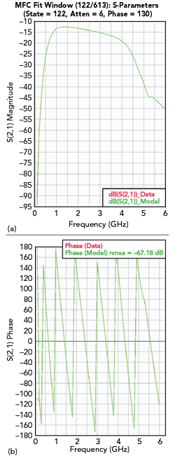
Figure 10 Subset of DPS+DSA S-parameters.

Figure 11 PA gain contours at a specific compression level.
To take into account the mismatch effects induced by the antenna on the PA, the latter was characterized using load-pull measurements. These measurements correspond to AM-AM and AM-PM characteristics for different frequencies and load impedances. Figure 11 shows the model versus measurement of gain contours at a specific input power.
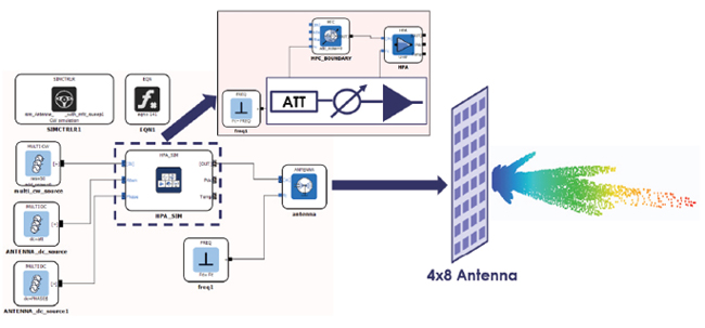
Figure 12 Active Antenna Schematic in comprehensive modeling workflow system (VISION).
Figure 12 shows the implementation of the active antenna architecture in a comprehensive modeling workflow system developed. Because the system is described in the form of command buses, the simulation takes into account the interaction between the 36 PAs connected to the 36 ports of the antenna. The active impedance presented by the antenna as a function of the antenna beam steering command is therefore indicated for each PA (see Figure 13).
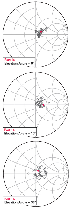
Figure 13 Reflection coefficient presented to 36 PAs for three different beam steering angles (0°, 10°, 30°).
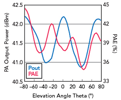
Figure 14 Pout/PAE vs. theta angle of PA connected to port 16 of the antenna.
Due to the load impedance dispersion, the PA’s performance is impacted. A variation of the delivered signal to the antenna in power and the phase may impact the beam steering and the system’s overall efficiency. Figure 14 shows the variation of these characteristics as a function of the position of the PA and the angle of the steered beam.
This analysis is possible due to the bilateral behavioral model, which takes into account the mismatch at the output of the PA and the solver, which manages a large number of elements of a complex architecture efficiently. Using this type of simulation, the system engineer can explore different architectures and circuit designs to evaluate the best combination to meet system specifications.
CONCLUSION
For several years, CAD tools have offered advanced features to adapt to the evolution of communication systems. The complexity of AAS architectures requires the system simulator to combine analyzes in different fields such as electromagnetic for the radiating panel, electrical for the front-end part and digital for the signal processing blocks. The size of the system is so large that simplifications are made for the modeling of the antenna and the front-end to obtain simulation results in a reasonable amount of time. This impacts the overall performance prediction and does not allow engineers to have sufficient confidence in this system simulation procedure.
The use of reliable behavioral models is increasingly required to fully exploit the system simulation and thus optimize the operating parameters and better size the RF circuits. This article presented an RF circuit behavioral modeling approach that is part of an industrial process that includes measurement or simulation data, quasi-automatic extraction and implementation in an in-house simulator and system simulators.
Moreover, this new approach has been demonstrated in the bilateral modeling of PA in the context of a simulation of the front-end of an active antenna comprising a large number of RF channels. This type of system simulation is fast and allows performance to be assessed based on operational parameters such as input power, frequency and antenna beam in elevation and azimuth angles. Also, other configurations can be evaluated in which the engineer can change antenna designs or RF circuits. These capabilities pave the way for co-design and system validation processes in simulation and enable system designers to reduce development time and market time significantly.
References
- Y. Wang, T. Steinbach, J. Klein and R. Anderl, “Integration of Model Based System Engineering into the Digital Twin Concept,” Procedia CIRP, Vol. 100, 2021, pp. 19–24.
- G. Gielen, “CAD Tools for Embedded Analog Circuits in Mixed-signal Integrated Systems on Chip, Computers and Digital Techniques,” IEEE Proceedings, 2005.
- J. Verspecht and D.E. Root, “Polyharmonic Distortion Modeling,” IEEE Microwave Magazine, Vol. 7, No. 3, June 2006, pp. 44–57.
- D. R. Morgan, Z. Ma, J. Kim, M. G. Zierdt and J. Pastalan, “A Generalized Memory Polynomial Model for Digital Predistortion of RF Power Amplifiers,” IEEE Transactions on Signal Processing, Vol. 54, No. 10, Oct. 2006, pp. 3852–3860.
- E. Ngoya and S. Mons, “Progress for Behavioral Challenges: A Summary of Time-domain Behavioral Modeling of RF and Microwave Subsystems,” IEEE Microwave Magazine, Vol. 15, No. 6, Sept.-Oct. 2014, pp. 91–105.
- R. Lamey, M. Thevenot, C. Menudier, E. Arnaud, O. Maas and F. Fezai, “Interleaved Parasitic Arrays Antenna (IPAA) for Active VSWR Mitigation in Large Phased Array Antennas With Wide-Angle Scanning Capacities,” IEEE Access, Vol. 9, 2021, pp. 121015-121030.