
Wideband (2 to 6 GHz) 4 × 4 and 8 × 8 Butler matrices without crossover circuits are implemented on a three metal-layer structure using hybrid couplers and phase shifters realized with elliptically-shaped coupling structures. A flexible design method for phase compensation is used based on the spacing of the hybrid couplers. Measurements agree with simulation, demonstrating the amplitude and phase performance of the ports. Compared to other Butler matrix configurations, the elliptical coupling structure without crossover circuits has an ultra-wide bandwidth of several octaves.
Butler matrices are used in a wide variety of antenna feed applications, such as beamforming networks. Conventional microstrip line Butler matrices1-4 use crossover circuits, which are relatively narrowband and difficult to route. Abbosh5,6 and Bialkowski5 describe an elliptical slot-coupled technology for the required 90-degree hybrid couplers and phase shifters. The slot-coupled technology is appropriate for broadband devices, and the multi-layer structure is helpful for designing Butler matrices without crossover circuits.7-9
In this work, wideband (2 to 6 GHz) 4 × 4 and 8 × 8 Butler matrices were designed based on slot-coupled technology. A flexible design method for phase compensation was used based on the spacing of the hybrid couplers. Accordingly, each component—the 90-degree hybrid couplers, phase shifters and phase-compensation circuits—can be individually simulated and optimized. Measurement results demonstrate a fractional bandwidth (FBW) of 100 percent.
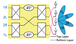
Figure 1 4 × 4 Butler matrix.
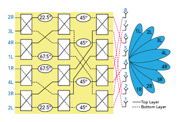
Figure 2 8 × 8 Butler matrix.
BUTLER MATRIX ARCHITECTURES
The Butler matrix is widely used in analog beamforming networks and is composed of N inputs and N outputs. In this article, N is 4 or 8. The number of 90-degree hybrid couplers equals (N/2) log2N, and the number of 45-degree phase shifters is (N/2) [log2N-1]. One of the N inputs produces uniform amplitudes at the output ports with a determined phase difference.7 The phase difference between output ports is different for every input port excitation; with four or eight specific values of the phase differences, the antenna array in a switched beamforming system synthesizes four or eight corresponding beams evenly pointing in different directions. The architectures of the 4 × 4 and 8 × 8 Butler matrices are illustrated in Figures 1 and 2, respectively, and their ideal operation summarized in Tables 1 and 2. A 4 × 4 Butler matrix is composed of four 90-degree hybrid couplers and two 45-degree phase shifters, while an 8 × 8 Butler matrix is composed of twelve 90-degree hybrid couplers, four 45-degree, two 22.5-degree and two 67.5-degree phase shifters.
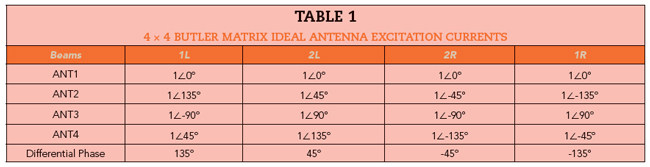
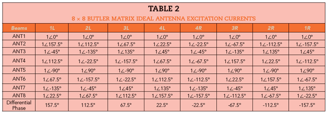

Figure 3 Elliptical coupling structures: hybrid coupler (a), phase shifter (b) and dimensions (c).
Elliptical slot-coupled technology is used for both the 90-degree hybrid couplers and phase shifters.5,6 The multi-layer structure enables the design of the Butler matrices without crossover circuits. Figure 3 shows the elliptically-shaped coupling structures of the hybrid coupler and phase shifter and their respective dimensions. The phase shifter of Figure 3b can be viewed as the hybrid coupler of Figure 3a with two ports terminated by open circuits. The last row of Tables 1 and 2 list the phase differences between adjacent antenna ports in Figures 1 and 2 for each beam direction.
Based on the above discussion, prototype 4 × 4 and 8 × 8 Butler matrices and their components were designed and simulated using a Rogers RO4003C substrate 1.016 mm thick, using a dielectric constant of 3.55 and a loss tangent of 0.0027.